S8NR-S / S8R-BB
Environment-resistant IP67 Power Supply / DC Blocking Box
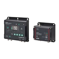
IP67 compliance and integrated functionality simplify the construction of power and safety circuits outside of control panels
Related Contents
- Features
- Lineup
- Specifications
- Dimensions
- Catalog / Manual / CAD / Software
last update: July 21, 2026
S8NR-S
S8NR-S09024-A1L0
| Model | S8NR-S09024-A1L0 | ||
|---|---|---|---|
| Efficiency *1 | 100 VAC Input *1 | 91% typ. | |
| 200 VAC Input *1 | 93% typ. | ||
| Input
conditions |
Input voltage allowable
range *3 |
85 to 264 VAC | |
| Frequency *3 | 50/60 Hz(47 to 63 Hz) | ||
| Input current | 1.2 A max. (100 VAC input) | ||
| 0.6 A max. (200 VAC input) | |||
| Power factor *1 | 0.9 min. | ||
| Leakage current | 0.5 mA max. (100 VAC input) | ||
| 1 mA max. (200 VAC input) | |||
| Inrush current
(for a cold start at 25°C) |
14 A typ. (100 VAC input) | ||
| 28 A typ. (200 VAC input) | |||
| Output
characteristics |
Rated output current | 3.8 A | |
| Rated output electric
power |
91.2 W | ||
| Maximum boost current | --- | ||
| Voltage variable range | No voltage adjustment | ||
| Ripple noise voltage *1 | 100 mV p-p max. (at rated input and outputs) | ||
| Static input fluctuation | 0.5% or less (at input 85 to 264 VAC, 100% load) *2 | ||
| Load fluctuation | 1.5% or less (at rated input, 0 to 100% Load) *2 | ||
| Ambient temperature
fluctuation |
0.05%/°C max. | ||
| Startup time *5 | 1,000 ms max *1 | ||
| Outputs hold time *5 | 30 ms typ. (at rated input and outputs) *1 | ||
| Functions | Overload protection | Yes, automatic reset | |
| Overvoltage protection | Yes, 130% or higher of rated output voltage, power shut off
(shut off the input voltage and turn on the input again) |
||
| Series connection | Not supported. | ||
| Parallel connection | Not supported. | ||
| Output indicator | Provided (Color: green) | ||
| DC OK Signal Output | Yes (MOS FET relay output 30 VDC max., 50 mA max.) | ||
| Withstand
voltage |
Dielectric strength
voltage |
2 kVAC for 1 min between (input terminals pins 1 and 3 collectively)
and (PE  , output terminals and signal terminals , output terminals and signal terminals
collectively) Detection current: 20 mA |
|
| 500 VAC for 1 min between (output terminals collectively) and
(signal terminals collectively) Detection current: 10 mA |
|||
| Insulation resistance | 100 MΩ min. at 500 VDC between (input terminals pins 1 and
3 collectively) and (PE , output terminals and
signal terminals collectively) |
||
| Environment | Ambient operating
temperature |
-25 to 70°C (with no condensation or icing) *4 | |
| Storage temperature | -25 to 85°C | ||
| Ambient operating
humidity |
5 to 95% | ||
| Storage humidity | 5 to 95% | ||
| Vibration resistance | 10 to 55 Hz, 0.375 mm single amplitude, 2h each in X, Y, and Z
directions, maximum 4.5G |
||
| Shock resistance | 150 m/s2 3 times each in ±X, ±Y, ±Z directions. | ||
| Reliability | MTBF | 135,000 hrs min. | |
| Expected life | 10 years | ||
| Construction | Weight (main unit) | 650 g max | |
| Cooling fan | blank | ||
| Protective structure *8 | IP65/IP66/IP67 | ||
| UL Enclosure Type *8*9 | Type 1 | ||
| Compatible
standards |
Harmonic suppression | Conforms to EN 61000-3-2 | |
| EMI | Conducted
EMI |
Compliant with EN 61204-3 Class B, EN 55011 Class B | |
| Radiated
EMI |
Compliant with EN 61204-3 Class B, EN 55011 Class B | ||
| EMS | EN 61204-3 high severity levels | ||
| Safety standards | UL 508 (Listing, Class2 Output: Per UL 1310), Pol3
EN/IEC 62477-1 (ES1 Output), OVCIII (<2,000 m), OVCII (2,000 m< and <3,000 m), Pol3 RCM (EN 61000-6-4) PELV (EN/IEC 60204-1) |
||
*1. Rated input/output conditions: at rated input voltage, rated frequency, rated output voltage, rated total output current, and maximum cutoff output current.
*2. 100% Load condition: at rated output voltage, rated total output current and maximum cutoff output current.
*3. Although some inverters have an output frequency of 50/60 Hz, they may cause internal temperature to rise and result in damage, if they are connected as the power source for the S8NR-S. Do not use the output from an inverter as the power source for the S8NR-S.
*4. For details, refer to Derating curve on Catalog.
*5. For details, refer to Inrush current, startup time, Outputs hold time on Catalog.
*6. Class2 Output is only for M12-A output
*7. When IO-Link communication is used, this product is classified as Class A.
*8. With waterproof caps attached to unused terminals.
*9. The IP rating (protection against dust and water) and the UL Enclosure Type (enclosure classification) are based on different evaluation criteria. The UL Enclosure Type 1 of this product is provided to meet the enclosure requirements of UL 508A and NFPA 79.
S8NR-S36024-A[]L[]-IL3
| Model | S8NR-S36024-A0L2-IL3 | S8NR-S36024-A2L1-IL3 | ||
|---|---|---|---|---|
| Efficiency *1 | 100 VAC Input *1 | 92% typ. (Power supply section only: 94% typ.) | ||
| 200 VAC Input *1 | 94% typ. (Power supply section only: 96% typ.) | |||
| Input
conditions |
Input voltage allowable
range *3 |
85 to 264 VAC | ||
| Frequency *3 | 50/60 Hz (47 to 63 Hz) | |||
| Input current | 4.0 A typ. (100 VAC input) | |||
| 2.0 A typ. (200 VAC input) | ||||
| Power factor | 0.9 min. | |||
| Leakage current | 0.5 mA max. (100 VAC input) | |||
| 1 mA max. (200 VAC input) | ||||
| Inrush current
(for a cold start at 25°C) |
7 A typ. (100 VAC input) | |||
| 14 A typ. (200 VAC input) | ||||
| Output
characteristics |
Number of branches | 4 (M12-L×2) | 4 (M12-A×2, M-12L×1) | |
| Maximum cutoff output
current (per branch) |
M12-A: 3.8 A (Class 2 Output) M12-L: 10 A | |||
| Total output current | 15 A | |||
| Voltage variable range | 24 to 28 V (adjustable with HMI or IO-Link communication) | |||
| Ripple noise voltage
(at rated input and outputs) *1 |
130 mV p-p max. (at 20 MHz of bandwidth) | |||
| Output leakage current | 10 mA max. | |||
| Static input fluctuation | 0.5% or less (at input 85 to 264 VAC, 100% load) *2 | |||
| Load fluctuation | 4.0% or less (at rated input, 0 to 100% Load) *2 | |||
| Ambient temperature
fluctuation |
0.05%/℃ max. | |||
| Startup time *5 | 2,000 ms max *1 | |||
| Outputs hold time *5 | 45 ms typ. (at rated input and outputs) *1 | |||
| Functions | Tripping functions | Abnormal
voltage tripping |
24.0 to 32.0 V (in 0.1 V unit) | |
| Abnormal
current tripping *2 |
Setting range: M12-A: 0.5 to 3.8 A (in 0.1 A unit),
M12-L: 0.5 to 10 A (in 0.1 A unit) |
|||
| Abnormal
total current tripping |
The output is shut off when the total output current
reaches 30 A for 1 s, 26 A for 2 s, 22.5 A for 5 s, 19.5 A for 10 s, or 18 A for 20 s. |
|||
| Undervoltage
detection functions |
Undervoltage
Detection |
Setting range: 18.0 to 28.0 V (in 0.1 V unit) | ||
| Maintenance
forecast monitor function |
Years up to
replacement time |
Setting range: 0.0 to 5.0 yr (in 0.5 yr unit) | ||
| Percentage
up to replacement time |
Setting range: 0.0 to 99.9% (in 0.1% unit) | |||
| Total running
time |
Setting range: 0 to 132 kh (in 1 kh unit) | |||
| Display functions | Output voltage
display |
Display range: 16.3 to 30.0 V
Display accuracy: 2% rdg ±1 digit max. |
||
| Output current
display |
Branch output current display range: 0.0 to 4.0 A (M12-A),
0.0 to 10.0 A (M12-L), Branch output peak current display range: 0.0 to 20.0 A Total output current display range: 0.0 to 40.0 A Display accuracy: M12-A 5% FS (4 A) ±1 digit max. M12-L 5% FS (10 A) ±1 digit max. |
|||
| Maintenance
forecast monitor display (yr) |
Display range: FUL (Full)/HLF (Half)/0.0 to 5.0 yrs | |||
| Maintenance
forecast monitor display (percentage) |
Display range: 0.0 to 99.9% | |||
| Total running
time |
Display range: 0 to 256 kh | |||
| Startup sequence | Setting range: 0.0 to 99.9 seconds (0.1-second Unit)
Default Branch output 1: 0.0 s Branch output 2: 0.4 s Branch output 3: 0.8 s Branch output 4: 1.2 s |
|||
| Shutdown sequence | Setting range: 0.0 to 99.9 s (0.1 s Unit) | |||
| Series connection | Not supported. | |||
| Parallel connection | Not supported. | |||
| Output indicator | Provided (Color: green) | |||
| Indication
monitor |
Measurement/
displayed details |
For details, refer to S8NR-S Users Manual (Man. No. T245). | ||
| Main display
area |
11-segment display (Color: white) | |||
| Channel display
area |
Seven-segment display (Color: green) | |||
| Unit display
area |
Provided (Color: yellow) | |||
| Withstand voltage | Dielectric strength voltage | 2 kVAC for 1 min between (input terminals pins 1 and
3 collectively) and (PE , branch output terminals and
IO-Link communications terminals collectively) Cutoff current: 20 mA |
||
| Insulation resistance | 100 MΩ min. at 500 VDC between (PE , branch output terminals and IO-Link communication terminals collectively)
and (input terminals pins 1 and 3 collectively) |
|||
| Environment | Ambient operating
temperature |
-25 to 70℃ (with no condensation or icing) *4 | ||
| Storage temperature | -25 to 85°C | |||
| Ambient operating
humidity |
5 to 95% | |||
| Storage humidity | 5 to 95% | |||
| Vibration resistance | 10 to 55 Hz, 0.375 mm single amplitude, 2h each in X, Y,
and Z directions, maximum 4.5G |
|||
| Shock resistance | 150 m/s2 3 times each in ±X, ±Y, ±Z directions. | |||
| Reliability | MTBF | 36,000 hours min. | ||
| Expected life | 10 years | |||
| Construction | Weight (main unit) | 1,800 g max | ||
| Cooling fan | blank | |||
| Protective structure
(dustproof and waterproof) *8 |
IP65/IP66/IP67 | |||
| UL Enclosure Type *8*9 | Type 1 | |||
| Compatible standards | Harmonic suppression | Conforms to EN61000-3-2 | ||
| EMI | Conducted
EMI |
Compliant with EN 61204-3 Class B, EN 55011 Class B | ||
| Radiated
EMI |
Compliant with EN 61204-3 Class B, EN 55011 Class B *7 | |||
| EMS | EN 61204-3 high severity levels | |||
| Safety standards | UL 508 (Listing, Class2 Output: Per UL 1310), Pol3 *6
CSA C22.2 No.107.1 (Class2 Output: Per CSA C22.2 No.223), Pol3 *6 EN/IEC 62477-1 (ES1 Output), OVCIII (<2,000 m), OVCII (2,000 m< and <3,000 m), Pol3 RCM (EN 61000-6-4) PELV (EN/IEC 60204-1) |
|||
*1. Rated input/output conditions: at rated input voltage, rated frequency, rated output voltage, rated total output current, and maximum cutoff output current.
*2. 100% Load condition: at rated output voltage, rated total output current and maximum cutoff output current.
*3. Although some inverters have an output frequency of 50/60 Hz, they may cause internal temperature to rise and result in damage, if they are connected as the power source for the S8NR-S. Do not use the output from an inverter as the power source for the S8NR-S.
*4. For details, refer to Derating curve on Catalog.
*5. For details, refer to Inrush current, startup time, Outputs hold time on Catalog.
*6. Class2 Output is only for M12-A output
*7. When IO-Link communication is used, this product is classified as Class A.
*8. With waterproof caps attached to unused terminals.
*9. The IP rating (protection against dust and water) and the UL Enclosure Type (enclosure classification) are based on different evaluation criteria. The UL Enclosure Type 1 of this product is provided to meet the enclosure requirements of UL 508A and NFPA 79.
S8NR-S60024-A[]L[]-IL3
| Model | S8NR-S60024-A0L3-IL3 | S8NR-S60024-A2L2-IL3 | ||
|---|---|---|---|---|
| Efficiency *1 | 200 VAC input *1 | 94% typ. (Power supply section only: 95% typ.) | ||
| Input
conditions |
Input voltage allowable
range *3 |
170 to 264 VAC | ||
| Frequency *3 | 50/60 Hz (47 to 63Hz) | |||
| Input current | 3.2 A typ. (200 VAC input) | |||
| Power factor | 0.9 min. | |||
| Leakage current | 1 mA max. (200 VAC input) | |||
| Inrush current
(for a cold start at 25°C) |
14 A typ. (200 VAC input) | |||
| Output
characteristics |
Number of branches | 6 (M12-L×3) | 6 (M12-A×2, M-12L×2) | |
| Maximum cutoff output
current (per branch) |
M12-A: 3.8 A (Class 2 Output) M12-L: 10 A | |||
| Total output current | 25 A | |||
| Voltage variable range | 24 to 28 V (adjustable with HMI or IO-Link communication) | |||
| Ripple noise voltage
(at rated input and outputs) *1 |
180 mV p-p max. (at 20 MHz of bandwidth) | |||
| Output leakage current | 10 mA max. | |||
| Static input fluctuation | 0.5% or less (at input 170 to 264 VAC, 100% load) *2 | |||
| Load fluctuation | 4.0% or less (at rated input, 0 to 100% Load) *2 | |||
| Ambient temperature
fluctuation |
0.05%/℃ max. | |||
| Startup time *5 | 2,000 ms max *1 | |||
| Outputs hold time *5 | 20 ms typ. (at rated input and outputs) *1 | |||
| Functions | Tripping
functions |
Abnormal
voltage tripping |
24.0 to 32.0 V (in 0.1 V unit) | |
| Abnormal
current tripping*2 |
Setting range: M12-A: 0.5 to 3.8 A (in 0.1 A unit),
M12-L: 0.5 to 10 A (in 0.1 A unit) |
|||
| Abnormal
total current tripping |
The output is shut off when the total output current reaches
43.5 A for 2 s, 37.5 A for 5 s, 32.5 A for 10 s, or 30 A for 20 s |
|||
| Undervoltage
detection functions |
Undervoltage
Detection |
Setting range: 18.0 to 28.0 V (in 0.1 V unit) | ||
| Maintenance
forecast monitor function |
Years up to
replacement time |
Setting range: 0.0 to 5.0 yr (in 0.5 yr unit) | ||
| Percentage
up to replacement time |
Setting range: 0.0 to 99.9% (in 0.1% unit) | |||
| Total running
time |
Setting range: 0 to 132 kh (in 1 kh unit) | |||
| Display
functions |
Output voltage
display |
Display range: 16.3 to 30.0 V
Display accuracy: 2% rdg ±1 digit max. |
||
| Output current
display |
Branch output current display range: 0.0 to 4.0 A (M12-A),
0.0 to 10.0 A (M12-L), Branch output peak current display range: 0.0 to 20.0 A Total output current display range: 0.0 to 40.0 A Display accuracy: M12-A 5% FS (4 A) ±1 digit max. M12-L 5% FS (10 A) ±1 digit max. |
|||
| Maintenance
forecast monitor display (yr) |
Display range: FUL (Full)/HLF (Half)/0.0 to 5.0 yrs | |||
| Maintenance
forecast monitor display (percentage) |
Display range: 0.0 to 99.9% | |||
| Total running
time |
Display range: 0 to 256 kh | |||
| Startup sequence | Setting range: 0.0 to 99.9 seconds (0.1-second Unit) Default
Branch output 1: 0.0 s Branch output 2: 0.4 s Branch output 3: 0.8 s Branch output 4: 1.2 s Branch output 5: 1.6 s Branch output 6: 2.0 s |
|||
| Shutdown sequence | Setting range: 0.0 to 99.9 s (0.1 s Unit) | |||
| Series connection | Not supported | |||
| Parallel connection | Not supported | |||
| Output indicator | Provided (Color: green) | |||
| Indication
monitor |
Measurement/
displayed details |
For details, refer to S8NR-S Users Manual (Man. No. T245). | ||
| Main display
area |
11-segment display (Color: white) | |||
| Channel
display area |
Seven-segment display (Color: green) | |||
| Unit display
area |
Provided (Color: yellow) | |||
| Withstand
voltage |
Dielectric strength voltage | 2 kVAC for 1 min between (input terminals pins 1 and
3 collectively) and (PE , branch output terminals and
IO-Link communications terminals collectively) Cutoff current: 20 mA |
||
| Insulation resistance | 100 MΩ min. at 500 VDC between (PE , branch output
terminals and IO-Link communication terminals collectively) and (input terminals pins 1 and 3 collectively) |
|||
| Environment | Ambient operating
temperature |
-25 to 70℃ (with no condensation or icing) *4 | ||
| Storage temperature | -25 to 85°C | |||
| Ambient operating
humidity |
5 to 95% | |||
| Storage humidity | 5 to 95% | |||
| Vibration resistance | 10 to 55 Hz, 0.375 mm single amplitude, 2h each in X, Y, and
Z directions, maximum 4.5G |
|||
| Shock resistance | 150 m/s2 3 times each in ±X, ±Y, ±Z directions. | |||
| Reliability | MTBF | 36,000 hours min. | ||
| Expected life | 10 years | |||
| Construction | Weight (main unit) | 1,800 g max | ||
| Cooling fan | blank | |||
| Protective structure
(dustproof and waterproof) *8 |
IP65/IP66/IP67 | |||
| UL Enclosure Type *8*9 | Type 1 | |||
| Compatible standards | Harmonic suppression | Conforms to EN61000-3-2 | ||
| EMI | Conducted
EMI |
Compliant with EN 61204-3 Class B, EN 55011 Class B | ||
| Radiated
EMI |
Compliant with EN 61204-3 Class B, EN 55011 Class B *7 | |||
| EMS | EN 61204-3 high severity levels | |||
| Safety standards | UL 508 (Listing, Class2 Output: Per UL 1310), Pol3 *6
CSA C22.2 No.107.1 (Class2 Output: Per CSA C22.2 No.223), Pol3 *6 EN/IEC 62477-1 (ES1 Output), OVCIII (<2,000 m), OVCII (2,000 m< and <3,000 m), Pol3 RCM (EN 61000-6-4) PELV (EN/IEC 60204-1) |
|||
*1. Rated input/output conditions: at rated input voltage, rated frequency, rated output voltage, rated total output current, and maximum cutoff output current.
*2. 100% Load condition: at rated output voltage, rated total output current and maximum cutoff output current.
*3. Although some inverters have an output frequency of 50/60 Hz, they may cause internal temperature to rise and result in damage, if they are connected as the power source for the S8NR-S. Do not use the output from an inverter as the power source for the S8NR-S.
*4. For details, refer to Derating curve on Catalog.
*5. For details, refer to Inrush current, startup time, Outputs hold time on Catalog.
*6. Class2 Output is only for M12-A output
*7. When IO-Link communication is used, this product is classified as Class A.
*8. With waterproof caps attached to unused terminals.
*9. The IP rating (protection against dust and water) and the UL Enclosure Type (enclosure classification) are based on different evaluation criteria. The UL Enclosure Type 1 of this product is provided to meet the enclosure requirements of UL 508A and NFPA 79.
IO-Link Specifications
| Item | Description |
|---|---|
| IO-Link Specifications | Ver 1.1.4 |
| Baud rate | COM3: 230.4 kbps (fixed) |
| Device profile | Common Profile, Locator |
| Minimum cycle time | COM3: 2.0 ms |
| Data length | PD size: 22 byte OD size: 1 byte (M-sequence type: TYPE_2_V) |
| Port class | ClassA |
Please contact your OMRON sales representative regarding the IO-Link setup file (IODD file).
IO-Link Indicator LEDs
The LED indications are prioritized in the order listed from top to bottom in this table.
When multiple statuses occur simultaneously, the indication listed higher in the table is displayed.
| Indicator | Status | Description |
|---|---|---|
| Green flashing (fast) | Locator active | Flashes twice and then turns OFF repeatedly at a 1-second cycle for 10 minutes.
This function allows the product to be visually identified among multiple devices at the installation site. For start/stop commands, refer to 5-2 IO-Link Communication Index List, Index 2 (System Command) in the S8NR-S Users Manual (Man. No. T245) |
| Red ON | Internal fault | An internal failure may have occurred in the product.
Restart the product. If the error reoccurs, replace the product. |
| Green flashing | Communication
established |
IO-Link communication is established. |
| OFF | Communication
not established |
No IO-Link communication. |
IO-Link Communication Index List
Refer to the S8NR-S Users Manual (Man. No. T245) for IO-Link communication Index list.
S8R-BB
Specifications
| Model | S8R-BB06[][] | S8R-BB10[][] | |||
|---|---|---|---|---|---|
| Input Conditions
(between 13 and -VI1,between +VI2 and -VI2) |
Rated voltage | 24 V | |||
| Allowable voltage range | 21.6 to 28.0 V | ||||
| Rated current | 6 A | 10 A | |||
| Output
Characteristics (between 14 and -VO1,+VO2 and -VO2) |
Rated voltage | 24 V | |||
| Allowable voltage range | 21.6 to 28.0 V | ||||
| Rated current | 6 A | 10 A | |||
| Signal
Conditions |
A1/A2 | Rated voltage | 24 V | ||
| Allowable voltage range | 21.6 to 26.4 V | ||||
| Rated current *1 | 50 mA | 100 mA | |||
| Power consumption *1 | 1.2 W | 2.2 W | |||
| EDM | Rated voltage | 24 V | |||
| Allowable voltage range | 30 V max. | ||||
| Rated current | 2 A | ||||
| Electrical
Characteristics |
Must operate voltage | 19.2 V max. | |||
| Must release voltage | 2.4 V min. | ||||
| Resistance
(between 13 and 14) *2 |
300 mΩ max. | ||||
| Operating
Characteristics |
Operating time *3 | 20 ms max. | 50 ms max. | ||
| Release time *3 | 20 ms max. | 50 ms max. | |||
| Response time *4 | 10 ms max. | 20 ms max. | |||
| Maximum
operating frequency |
Mechanical | 36,000 operations/h | 18,000 operations/h | ||
| Rated load | 1,800 operations/h | ||||
| Insulation
performance |
• Dielectric strength
voltage600 VAC 1 min. Detection current 20 mA • Insulation resistance 500 VDC 20 MΩ min. |
S8R-BB[][]A1
Between <Input and output terminals (grouped, FE excluded)> and <EDM/coil terminal pins 6, 7, and 8 (grouped)> Between <Input and output terminals (grouped, FE excluded)> and <EDM/coil terminal pins 1 and 2 (grouped)> Between <Input and output terminals (grouped, FE excluded)> and <FE> Between <EDM/coil terminal pins 6, 7, and 8 (grouped)> and <FE> Between <EDM/coil terminal pins 1 and 2 (grouped)> and <FE> S8R-BB[][]A2 Between <Input and output terminals (grouped, FE excluded)> and <Coil terminals (grouped)> Between <Input and output terminals (grouped, FE excluded)> and <EDM terminals (grouped)> Between <Input and output terminals (grouped, FE excluded)> and <FE> Between <Coil terminals (grouped)> and <FE> Between <EDM terminals (grouped)> and <FE> |
|||
| Contact switching
performance |
Resistance load | 24 VDC 6 A | 24 VDC 10 A | ||
| Inductive load *5 | 24 VDC 1 A | 24 VDC 2 A | |||
| Reliability | Electrical Durability *5 | 100,000 operations min.
(Under the above load conditions) |
100,000 operations min.
(Under the above load conditions) |
||
| Mechanical Durability *6 | 10,000,000 operations min. | ||||
| Environment | Ambient operating
temperature |
-25 to 55°C (with no condensation or icing) | |||
| Storage temperature | -25 to 65°C | ||||
| Ambient operating humidity | 5 to 85% max. | ||||
| Storage humidity | 5 to 85% max. | ||||
| Altitude | 3,000 m max. | ||||
| Vibration resistance *7 | 10 to 55 Hz, 0.375 mm single
amplitude 3 times in X, Y, Z directions 2h each |
10 to 55 Hz, 0.375 mm single
amplitude in X, Y, Z directions 2h each (excluding the front horizontal direction) |
|||
| Shock resistance *7 | 150m/s2, 3 times each in ±X,
±Y, ±Z directions. |
150m/s2, 3 times each in ±X,
±Y, ±Z directions. (excluding front horizontal mounting) |
|||
| Construction | Weight (main unit) | 650 g max. | 900 g max. | ||
| Cooling fan | None | ||||
| Protective structure
(dustproof and waterproof) *8 |
IP65/IP66/IP67 | ||||
| UL Enclosure Type *8*9 | Type 1 | ||||
| Standards | Safety standards | UL 508 (Listing). Pol3
CSA C22.2 No.107.1. Pol3 |
|||
| CE marking
(RoHS Directive) |
EN IEC 63000 | ||||
Note: 1. The above values are initial values.
Note: 2. Electrical characteristics and operating characteristics are values at an ambient temperature of 23°C.
*1. Measurement conditions: Rated voltage
*2. Measurement conditions: S8R-BB06[][]: 5 V, 1 A, voltage drop method
S8R-BB10[][]: 5 V, 10 mA, voltage drop method
*3. Measurement conditions: Rated voltage
Ambient temperature: 23°C
Bounce time is not included.
*4. Measurement conditions: Rated voltage
Ambient temperature: 23°C
The time from when the coil voltage is turned OFF until the a-contact turns OFF, including bounce time.
*5. Values under the following conditions: Contact voltage: 24 V
Coil voltage: 24 V
Switching frequency: 1,800 operations/h
Ambient temperature: 25°C
Inductive load performance: S8R-BB06[][]: L/R=48 ms
S8R-BB10[][]: L/R=96 ms
*6. Switching frequency: 36,000 operations/h
*7. For installation, be sure to check Installation described.
*8. With waterproof caps attached to unused terminals.
*9. The IP rating (protection against dust and water) and the UL Enclosure Type (enclosure classification) are based on different evaluation criteria. The UL Enclosure Type 1 of this product is provided to meet the enclosure requirements of UL 508A and NFPA 79.
last update: July 21, 2026