K7TM
Heater Condition Monitoring Device
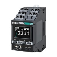
Predictive maintenance by monitoring heater condition
Related Contents
- Features
- Lineup
- Specifications
- Dimensions
- Catalog / Manual / CAD / Software
last update: April 1, 2022
Ratings and Specifications
| Item | Specifications | |
|---|---|---|
| Operation
power supply |
Power supply voltage
and frequency |
K7TM-A2MA: 100 to 240 V AC, 50/60 Hz
K7TM-A2MD: 24 V AC, 50/60 Hz, 24 V DC |
| Operating power
supply voltage range |
85% to 110% of the rated voltage | |
| Operating frequency
range |
45 to 65 Hz | |
| Power consumption | K7TM-A2MA: 8.5 VA max. (100 to 240 V AC) | |
| K7TM-A2MD: 5.2 VA max. (24 V AC)/ 2.9 W max. (24 V DC) | ||
| Recommend external
fuse |
T2A, time delay, high-breaking capacity | |
| Ambient operating temperature | -10 to 55°C | |
| Ambient operating humidity | 25% to 85% | |
| Storage temperature | -20 to 65°C (with no condensation or icing) | |
| Altitude | 2,000 m max. | |
| Insulation resistance | 20 mΩ min.
Between all external terminals and case; Between all power supply terminals and all other terminals; Between (all voltage input terminals + all CT input terminals) and (all communications terminals + all transistor terminals); Between all voltage input terminals and all CT input terminals; Between the channels of voltage inputs; Between the channels of CT inputs |
|
| Dielectric strength | 2,000 V AC for 1 minute
Between all external terminals and case; Between all power supply terminals and all other terminals; Between (all voltage input terminals + all CT input terminals) and (all communications terminals + all transistor terminals); Between all voltage input terminals and all CT input terminals; Between the channels of voltage inputs; Between the channels of CT inputs |
|
| Vibration resistance | Frequency 10 to 55 Hz, 0.35-mm single amplitude, acceleration 50 m/s²,
10 sweeps of 5 min each in X, Y, and Z directions |
|
| Shock resistance | 100 m/s2, 3 times each in X, Y, and Z axes, 6 directions | |
| Degree of protection | IP20 | |
| Terminal block type | Push-In Plus | |
| Exterior color | Black (Munsell N 1.5) | |
| Mounting | DIN Track | |
| Weight | Approx. 200 g | |
| Wiring
material |
Wire type | Solid or Stranded wire |
| Wiring material | Copper | |
| Recommended wires | 0.25 to 1.5 mm2
AWG 24 to AWG 16 |
|
| Stripping length
(without ferrules) |
8 mm | |
| Installation environment | Operation voltage: EN/IEC 61010-1 Pollution Degree 2, Overvoltage category II | |
| Measurement circuit: EN/IEC 61010-2-030 Pollution Degree 2, CAT II 600 V or
CAT III 300 V |
||
| Industrial electromagnetic
environment |
EN/IEC 61326-1 Industrial electromagnetic environment | |
Measurement Specifications
| Item | Specifications | |
|---|---|---|
| Input range | Current
Rated 5 A AC: 0.00 to 5.00 A AC Rated 25 A AC: 0.0 to 25.0 A AC Rated 100 A AC: 0.0 to 100.0 A AC Rated 200 A AC: 0.0 to 200.0 A AC Rated 400 A AC: 0.0 to 400.0 A AC Rated 600 A AC: 0.0 to 600.0 A AC Rated frequency: 50/60 Hz Voltage Rated 120 V AC: 0.0 to 120.0 V AC Rated 240 V AC: 0.0 to 240.0 V AC Rated 480 V AC: 0.0 to 480.0 V AC Rated 600 V AC: 0.0 to 600.0 V AC Rated frequency: 50/60 Hz |
|
| Measurable range | Current
Rated 5 A AC: 0.00 to 5.50 A AC Rated 25 A AC: 0.0 to 27.5 A AC Rated 100 A AC: 0.0 to 110.0 A AC Rated 200 A AC: 0.0 to 220.0 A AC Rated 400 A AC: 0.0 to 440.0 A AC Rated 600 A AC: 0.0 to 650.0 A AC Voltage Rated 120 V AC: 0.0 to 132.0 V AC Rated 240 V AC: 0.0 to 264.0 V AC Rated 480 V AC: 0.0 to 528.0 V AC Rated 600 V AC: 0.0 to 660.0 V AC |
|
| Measurement accuracy | Absolute accuracy of voltage/current: ±0.5% FS ±1 digit to the
input range Conditions: • When sine waves are input continuously • Variations in CTs are not included. Repeat accuracy of resistance value (reference value): ±1% rdg ±1 digit Conditions: • When sine waves are input continuously • Variations in CTs are not included. |
|
| Measurement target | Resistance heating heater | |
| CH1 voltage input
CH2 voltage input |
Measurement accuracy | ±0.5% FS ±1 digit |
| Input range | 0 to 600 V AC, 50/60 Hz | |
| Recommend external fuse | Class CC, Class J, or Class T with a rated current of 7 A or less | |
| CH1 CT input
CH2 CT input |
Measurement accuracy | ±0.5% FS ±1 digit |
| Input range | 0 to 600 A AC, 50/60 Hz | |
Output Specifications of Transistor Output Terminals
| Item | Specifications | |
|---|---|---|
| Transistor output
(Alarm output, Output at error) |
Contact form | NPN open collector (normally close) |
| Rated voltage | 24 V DC (maximum voltage: 26.4 V DC) | |
| Maximum current | 50 mA | |
| Leakage current
when power turning OFF |
0.1 mA max. | |
| Residual voltage | 1.5 V max. | |
Communications Specifications
| Item | Specifications | |
|---|---|---|
| RS-485
communications 1 RS-485 communications 2 |
Transmission path
connection method |
RS-485: Multidrop |
| Communications method | RS-485 (2-wire, half duplex) | |
| Cable length | When the baud rate is 115.2 kbps or less, the maximum length is
500 m with a twisted-pair cable. When the baud rate is 230.4 kbps, the maximum length is 200 m with a twisted-pair cable. |
|
| Protocol | Modbus RTU | |
| Baud rate | 9.6 kbps/19.2 kbps/38.4 kbps/57.6 kbps/115.2 kbps/230.4 kbps | |
| Data length | Always 8 bits | |
| Stop bits | Always 1 bit (with parity being even/odd)
Always 2 bits (with parity being none) |
|
| Connection configurations | 1:1 or 1:N | |
| Maximum number of Units | 32 Units (including the host system) | |
| Parity | None/Even/Odd | |
| Send wait time | 0 to 99 ms | |
Ratings and Specifications of CT *1
| Model | K6CM-
CICB005(-C) |
K6CM-
CICB025(-C) |
K6CM-
CICB100(-C) |
K6CM-
CICB200(-C) |
K6CM-
CICB400(-C) |
K6CM-
CICB600 |
|---|---|---|---|---|---|---|
| Construction | Internal split type | |||||
| Primary-side rated current | 5 A | 25 A | 100 A | 200 A | 400 A | 600 A |
| Rated voltage | 600 V AC | |||||
| Secondary winding | 3,000 turns | 6,000 turns | 9,000 turns | |||
| Insulation resistance | Between output terminal and case: 50 mΩ min | |||||
| Dielectric strength | Between output terminal and case: 2,000 V AC for 1 minute | |||||
| Protective element | 7.5 V clamp element | |||||
| Allowable number of
attachments and detachments |
100 times | |||||
| Diameter of wire attachable
*2 |
7.9 mm dia.
max. |
9.5 mm dia.
max. |
14.5 mm dia.
max. |
24.0 mm dia.
max. |
35.5 mm dia. max. | |
| Operating temperature and
humidity range |
-20 to 60°C, 25% to 85% (with no condensation or icing) | |||||
| Storage temperature and
humidity range |
-30 to 65°C, 25% to 85% (with no condensation or icing) | |||||
| Supplied cable length | 2.9 m | |||||
| Supplied cable terminal | K7TM side: Ferrule, CT side: Round crimp terminal | |||||
| Degree of protection | IP20 | |||||
*1. To comply with UL certification, refer to Conformance to Safety Standards (Data Sheet).
*2. When you use a flat wire, refer to the outline dimensional drawing of the relevant CT and use a CT with a larger
However, use the CT within the range of its rated current.
*2. When you use a flat wire, refer to the outline dimensional drawing of the relevant CT and use a CT with a larger
However, use the CT within the range of its rated current.
last update: April 1, 2022