S8V-CP
DC Electronic Circuit Protector (24 VDC 4 Outputs/8 Outputs Type)
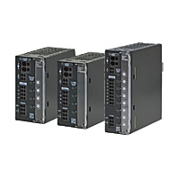
Simplified safety design of DC circuits Reliable DC circuit protection in the event of short circuits or overcurrent Saves space even with multi-channels Sequential start-up of outputs to avoid start-up trouble
Related Contents
- Features
- Lineup
- Specifications
- Dimensions
- Catalog / Manual / CAD / Software
last update: May 7, 2026
Ratings, Characteristics, and Functions
| Model | S8V-CP0424 | S8V-CP0424S | S8V-CP0824 | ||
|---|---|---|---|---|---|
| Number of Outputs | 4 | 4 | 8 | ||
| UL Class 2 output | No | Yes | No | ||
| I/O
character- istics |
Rated input voltage
(Input voltage allowable range) |
24 VDC
(20 to 30 VDC) |
24 VDC
(20 to 28.8 VDC) |
24 VDC
(20 to 30 VDC) |
|
| Allowable input current *1 | 40 A | 15.2 A | 70 A | ||
| Max. rated output current (per
output) |
10 A | 3.8 A | 10 A | ||
| Internal voltage drop *2 | 180 mV typ. | 180 mV typ. | 200 mV typ. | ||
| Output leakage current | 10 mA max. | ||||
| Power
consumption (at input voltage 24 VDC) *3 |
When all outputs
are connected |
8 W typ.
(at 10 A x 4 CH) |
4 W typ.
(at 3.8 A x 4 CH) |
15 W typ.
(at 10 A x 7 CH) |
|
| When all outputs
are tripped |
0.7 W typ. | 0.8 W typ. | 1.1 W typ. | ||
| Start-up
time *4 |
Initialization time | 250 ms typ. | |||
| Start-up delay
time |
50 ms to 5 s | ||||
| Functions *5 | Current
tripping function *6 |
Rated output
current |
2 A, 3 A, 4 A, 6 A,
8 A, 10 A |
3.8 A | 2 A, 3 A, 4 A, 6 A,
8 A, 10 A |
| Cutoff current | 2.5 A, 3.5 A, 4.5 A,
6.5 A, 8.5 A, 10.5 A |
3.8 A | 2.5 A, 3.5 A, 4.5 A,
6.5 A, 8.5 A, 10.5 A |
||
| Over voltage tripping function *6 | No | Yes | No | ||
| Push button (ON/OFF/RESET)
with indicator |
Yes (LED colors: Red/Green/Yellow) | ||||
| Reset signal input (RST) | Yes (High level: 20 to 30 VDC, Low level: 0 to 5 VDC) | ||||
| Alarm signal output (ALM1/
ALM2) |
Yes (MOS FET relay output 30 VDC max., 50 mA max.) | ||||
| Insulation | Dielectric strength | 1.0 kVAC for 1 min (between all terminals and DIN rail
mounting parts), current cutoff 20 mA |
|||
| Insulation resistance | 100 MΩ min. (between all terminals and DIN rail mounting
parts) at 500 VDC |
||||
| Environment | Ambient operating temperature | -25 to 70°C (Derating is required according to the temperature.)
(with no condensation or icing) |
|||
| Storage temperature | -40 to 85°C (with no condensation or icing) | ||||
| Ambient operating humidity | 5% to 96% (storage humidity: 5% to 96%) | ||||
| Vibration resistance | 10 to 55 Hz, maximum 5 G, 0.42 mm half amplitude for 2 h
each in X, Y, and Z directions |
||||
| Shock resistance | 294 m/s2, 3 times each in ±X, ±Y, ±Z directions | ||||
| Reliability | MTBF *7 | 135,000 hrs typ. | 60,000 hrs typ. | 60,000 hrs typ. | |
| Life expectancy *8 | 10 years min. | ||||
| Construction | Weight | 160 g max. | 170 g max. | 420 g max. | |
| Cooling fan | No | ||||
| Degree of protection | IP20 by IEC60529 | ||||
| Standards | EMI | Conforms to EN 61000-6-3 | |||
| EMS | Conforms to EN 61000-6-2 | ||||
| Safety standards | UL 508 (CSA22.2 No.14-10) Listing Pol2
UL 2367 Recognition (Max. 100W per output, per Class 2 limitations) Pol2 *9 CE (EN 61000-6-2, EN 61000-6-3) |
||||
*1. For power input terminals, use 35 A max. per pole.
*2. A voltage drop will occur in the S8V-CP. Consider the voltage drop at the output.
*3. When selecting the power supply, be sure to include the power consumption of the S8V-CP and not just the power consumption of the load.
*4. Outputs start in order from +VO1 to +VO8. +VO1 starts after the initialization time. Start-up delay time of each output is automatically decided depending on the load. If the start-up delay time is over 5 s, the next output is forcibly started.
*5. Refer to Tripping Functions for details.
*6. Refer to Current Tripping Characteristics and Current and Voltage Tripping Characteristics for details.
*7. MTBF is calculated according to JEITA RCR-9102.
*8. Refer to Recommended Replacement Periods and Periodic Replacement for Preventive Maintenance on Catalog for details.
*9. UL Class 2 output applies for the S8V-CP0424S model only.
Tripping Functions
Current tripping
If the output current of each output exceeds the current tripping, the output is tripped by a semiconductor switch (MOS FET) in accordance with the current tripping characteristic.
Over voltage tripping
With the S8V-CP0424S, if the input voltage exceeds 28.8 V, all outputs are tripped by a semiconductor switch (MOS FET).
If the input voltage becomes 28.8 V or less, all outputs automatically return to the previous state.
Reset Signal Input (RST)
Turning ON all outputs during in the Current tripping (enable to reset) state is called reset. Output terminals in the Current tripping (enable to reset) state can be reset by an external input. As shown in the following figure, input a high level signal of 0.5 s or more and reset.
Input voltage: 30 VDC max.
Input impedance: 22 kΩ
Note: 1. When Reset signal input terminal is used, a miss operation of reset may occur by a noise coming from the cable. Do not make an instable potential of Reset signal input terminal.
Alarm Signal Output (ALM1/ALM2)
If any of the output is tripped, the MOS FET relay is turned OFF. The signal output comprises of MOS FET relays and therefore, does not have polarity.
Input voltage: 30 VDC max., Input current: 50 mA max.
Residual voltage when ON: 2 V max.
Leakage current when OFF: 0.1 mA max.
Note:
1. Alarm signal output is not equipped with an internal current limiting circuit, so be sure that the current flowing to the alarm signal output terminals does not exceed 50 mA.
2. Be sure to check that the Alarm signal outputs are working normally after wiring.
Output Status
The status of each output can be identified by the indicator or alarm signal output.
The status of each output is saved when the power is turned OFF. When the power is turned ON again, the status transits to that saved after initialization.
All outputs are set to Output ON state by default.
| Indicator | Alarm
Signal Output |
Output | Status Name | Status Transition
by Push Button |
Status Transition
by Reset Signal Input |
|
|---|---|---|---|---|---|---|
| Color | Status | |||||
| --- | OFF | OFF | OFF | Initialization | --- | --- |
| Green | ON | ON | ON | Output ON | Manually output OFF | --- |
| Yellow | ON | ON | ON | Over current *1 | Manually output OFF | --- |
| Red | ON | OFF | OFF | Manually output OFF | Output ON | --- |
| Red | Blinking | OFF | OFF | Current tripping
(Disable to reset) *2 |
--- | --- |
| Yellow | Blinking | OFF | OFF | Current tripping
(Enable to reset) |
Manually output OFF | Output ON
(transition due to positive pulse longer than 0.5 s) *5 |
| Red | Blinking
fast |
OFF | OFF | Over voltage tripping *3
Internal error detection *4 |
--- | --- |
*1. Each output transits automatically to Current tripping (disable to reset) state according to the Current tripping characteristics.
*2. The status remains on Current tripping (disable to reset) state during 500 ms to 20 s in order to protect the internal parts from heat.
After that, the status automatically transits to Current tripping (enable to reset) state.
*3. S8V-CP0424S only
*4. If an internal fuse blows, or an internal memory error occurs, the output will be disconnected.
*5. Always remove the cause of the output first and then reset the alarm when abnormal tripping operates.
Engineering Data
Derating Curves
S8V-CP0424
S8V-CP0424S
S8V-CP0824
Current Tripping Characteristics
S8V-CP0424, S8V-CP0824
Note: If the power rating of the power supply unit is insufficient, the voltage of all the outputs may drop due to the overcurrent protection characteristic of the power supply unit.
To achieve tripping according to the above characteristic, select the required power rating of the power supply unit by adding the cutoff current value in addition to the normally flowing output current and the power consumption of the S8V-CP.
(Please refer to Recommended power supply unit)
Current and Voltage Tripping Characteristics
S8V-CP0424S
Note:
1. Input voltage 24 to 28.8 VDC tripping current is decreased to less than 3.2 A in accordance with the current and voltage tripping characteristic.
2. Current tripping takes place between 250 ms to 5 s.
3. If the power rating of the power supply unit is insufficient, the voltage of all the outputs may drop due to the overcurrent protection characteristic of the power supply unit. Please refer to Recommended power supply unit.
Recommended power supply unit
In order to cut off only the abnormal circuit, please select a power supply unit using the table below.
| S8V-CP | Rated output current setting of S8V-CP | Power supply |
|---|---|---|
| S8V-CP0424S | Not required (3.8 A fixed) | S8VK-S24024
S8VK-X24024[]-EIP S8VK-WA24024 |
| S8V-CP0424 | Set all outputs to 4 A or less | S8VK-S48024
S8VK-X48024[]-EIP S8VK-WA48024 |
| Set either output to 6 A or more | S8VK-WA96024 | |
| S8V-CP0824 | Set all outputs to 6 A or less | S8VK-WA96024 |
| Set either output to 8 A or more | S8VK-WA20224 |
Note:
1. Recommended when using all outputs. Please ask your OMRON representative for recommended power supply units when using under other conditions.
2. When using the S8VK-WA20224, make sure that the input current is less than or equal to the allowable input current of the S8V-CP0824.
3. Power supply units of the same series as the recommended model, with higher capacity ratings, can also be used in combination.
last update: May 7, 2026