K8DT-PH
Phase-sequence Phase-loss Relay
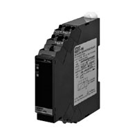
Our Value Design Products Increase the Value of Your Control Panels. Protect motors and other equipment from unstable voltages in the power supply system. Protect motors and other equipment by detecting phase sequence and phase loss for three-phase power supplies.
Related Contents
- Features
- Lineup
- Specifications
- Dimensions
- Catalog / Manual / CAD / Software
last update: March 1, 2019
Ratings
| Rated input voltage | 3-phase, 200 to 480 VAC (3-wire) | |
|---|---|---|
| Input load | Approx. 2.6 VA | |
| Rated insulation
voltage |
528 VAC | |
| Operating
time |
Phase
sequence |
0.1 s±0.05 s |
| Phase loss | 0.1 s max.
(when the voltage changes rapidly from 100% to 0% of rated voltage) |
|
| Reset method | Automatic reset | |
| Indicators | Power (PWR): Green,
Output (OUT): Yellow |
|
| Output form | Relay Output: SPDT contact
Transistor Output: 1 |
|
| Output relay ratings | Rated load
5 A at 250 VAC (Resistive load) 5 A at 30 VDC (Resistive load) 1 A at 250 VAC (Inductive load) 0.2 A at 48 VDC (Inductive load) Minimum load: 5 VDC, 10 mA (reference values) Mechanical life: 10 million operations min. Electrical life: 5 A at 250 VAC or 30 VDC: 50,000 operations 3 A at 250 VAC or 30 VDC: 100,000 operations |
|
| Transistor output
ratings |
Rated voltage: 24 VDC (maximum voltage: 26.4 VDC)
Maximum current: 50 mA DC |
|
| Ambient operating
temperature |
-20 to 60°C (with no condensation or icing) | |
| Storage temperature | -25 to 65°C (with no condensation or icing) | |
| Ambient operating
humidity |
25% to 85% RH (with no condensation) | |
| Storage humidity | 25% to 85% RH (with no condensation) | |
| Altitude | 2,000 m max. | |
| Applicable wires | Stranded wires, solid wires, or ferrules | |
| Applicable wire size | 0.25 to 1.5 mm2 (AWG24 to AWG16) | |
| Wire insertion force | 8 N max. for AWG20 wire | |
| Screwdriver
insertion force |
15 N max. | |
| Wire stripping length | 8 mm | |
| Ferrule length | 8 mm | |
| Recommended flatblade
screwdriver |
XW4Z-00B (Omron)
SZF 0.4 × 2.5 (Phoenix Contact) 210-719 (Wago) SDI 0.4 × 2.5 × 75 (Weidmuller) |
|
| Current capacity | 10 A (per pole) | |
| Number of
insertions |
50 times | |
| Case color | N1.5 | |
| Case material | PC, UL 94 V-0 | |
| Weight | Approx. 100 g | |
| Mounting | Mounts to DIN Track, or screw mounting | |
| Dimensions | 17.5 × 90 × 90 mm (W×D×H) | |
Specifications
| Input frequency
range |
45 to 65 Hz | |
|---|---|---|
| Overload capacity | Continuous 528 V | |
| Phase loss detection
level |
80%±10% of rated input Calculation Formula
= 1 - ((Highest phase-to-phase voltage - Lowest phase-to-phase voltage)/ Average three-phase phase-to-phase voltage) |
|
| Applicable
standards |
Conforming
standards |
EN 60947-5-1
Installation environment (pollution level 2, Overvoltage category III) |
| EMC | EN 60947-5-1 | |
| Safety
standards |
UL 60947-5-1 (Listing), Korean Radio Waves Act (Act 10564),
CCC (GB/T 14048.5), LR (Category ENV1.2) |
|
| Insulation resistance | 20 MΩ min.
Between external terminals and case Between input terminals and output terminals |
|
| Dielectric strength | 2,000 VAC for one minute
Between external terminals and case Between input terminals and output terminals |
|
| Impulse withstand
voltage |
6 kV (between live terminals and exposed, non-charged metal parts) | |
| Noise immunity | 1,500 V power supply terminal common/normal mode
Square-wave noise of 1 μs/100 ns pulse width with 1-ns rise time |
|
| Vibration resistance | Frequency: 10 to 55 Hz, 0.35-mm single amplitude
10 sweeps of 5 min each in X,Y, and Z directions |
|
| Shock resistance | 100 m/s2, 3 times each in 6 directions along 3 axes | |
| Degree of protection | Terminals: IP20 | |
last update: March 1, 2019