Discontinued On Mar. 2016
K3TF
Digital Panel Meter
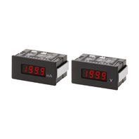
Easy-to-use, Low-cost Digital Panel Meter that Accepts AC Input
* Information in this page is a reference that you created on the basis of information in the product catalog before the end of production, may be different from the current situation, such as goods for / supported standards options / price / features of the product. Before using, please check the compatibility and safety system.
Related Contents
- Features
- Lineup
- Specifications
- Dimensions
- Catalog / Manual / CAD / Software
last update: April 4, 2013
Ratings
| Supply voltage | 100 to 120 VAC (50/60 Hz); 200 to 240 VAC (50/60 Hz) |
|---|---|
| Operating voltage range | -15% to +10% of supply voltage |
| Power consumption | 4 VA (at max. load) |
| Insulation resistance | 10 MΩ min. (at 500 VDC) between external terminal and case |
| Dielectric strength | 2,000 VAC min. for 1 min between input terminal and power supply
2,000 VAC min. for 1 min between external terminal and case |
| Noise immunity | ±1,500 V on power supply terminals in normal or common mode |
| Vibration resistance | Malfunction: 10 to 55 Hz, 0.5-mm single amplitude for 10 min each in X, Y, and Z directions
Destruction: 10 to 55 Hz, 0.75-mm single amplitude for 2 hrs each in X, Y, and Z directions |
| Shock resistance | Malfunction: 98 m/s2 for 3 times each in 6 directions
Destruction: 294 m/s2 for 3 times each in 6 directions |
| Ambient temperature | Operating: -10° to 55°C (with no icing)
Storage: -20° to 65°C (with no icing) |
| Ambient humidity | Operating: 35% to 85% (with no condensation) |
| Ambient operating atmosphere | No corrosive gas |
| EMC | (EMI) EN61326+A1 Industry
Emission Enclosure: CISPR 11 Group 1 class A: CISRP16-1/-2 Emission AC Mains: CISPR 11 Group 1 class A: CISRP16-1/-2 (EMS) EN61326+A1 Industry Immunity ESD: EN61000-4-2: 4 kV contact discharge (level 2) 8 kV air discharge (level 3) Immunity RF-interference: EN61000-4-3: 10 V/m (amplitude-modulated,80 MHz to 1 GHz) (level 3) Immunity Fast Transient Noise: EN61000-4-4: 2 kV (power line) (level 3) Immunity Burst Noise: 1 kV line to line (I/O signal line) Immunity Surge: EN61000-4-5: 1 kV line to line 2 kV line to ground (power line) Immunity Conducted Disturbance EN61000-4-6: 3 V (0.15 to 80 MHz) (level 2) Immunity Voltage Dip/Interrupting EN61000-4-11: 0.5 cycles, 0, 180°, 100% (rated voltage) |
| Approved standard | UL508,CSA22.2;
Conforms to EN61326+A1, EN61010-1 (IEC61010-1) Conforms to VDE0106/P100 (finger protection) when the terminal cover is mounted. |
Characteristics
| Input signal | AC voltage/current |
|---|---|
| A/D conversion method | Double integral method |
| Root-mean-square value indication | Root-mean-square value of half-wave rectified current detected |
| Sampling period | 2.5 times/s |
| Display refresh period | 2.5 times/s |
| Max. displayed digits | 3 1/2 digits (1999) |
| Display | 7-segment red LED |
| Decimal point display position | Selected with slide switch *1 |
| Overflow display | Overflow: 1[][][] |
| Zero suppression | Not supported. |
| External control | Process value hold (terminals on rear panel short-circuited) |
| Degree of protection | Front panel: IEC IP51 *2
Case: IEC IP20 Terminals: IEC IP00 |
*2. IP51 is maintained when the water-resistive soft cover and bracket are used. IP50 will be, however, maintained
without these water-resistive accessories.
Measuring Ranges
| Monitor | Input
range |
Measuring
range |
Max.
resolution |
Input
impedance |
Accuracy | Max. permissible load |
|---|---|---|---|---|---|---|
| Line monitor | AC voltage | 0 to 199.9 V | 100 mV | 10 MΩ | ±0.3%rdg ±1 digit *1 | 500 V |
| 0 to 400 V | 1 V | 10 MΩ | ±0.3%rdg ±1 digit | 500 V | ||
| Signal
monitor |
AC voltage | 0 to 199.9 mV | 100 μV | 10 MΩ | ±0.3%rdg ±1 digit | 250 V |
| 0 to 1.999 V | 1 mV | 10 MΩ | ±0.3%rdg ±1 digit | 250 V | ||
| 0 to 19.99 V | 10 mV | 1 MΩ | ±0.3%rdg ±1 digit | 250 V | ||
| AC current | 0 to 1.999 mA | 1 μA | 100 Ω | ±0.5%rdg ±1 digit | 50 mA | |
| 0 to 19.99 mA | 10 μA | 10 Ω | ±0.5%rdg ±1 digit | 150 mA | ||
| 0 to 199.9 mA | 100 μA | 1 Ω | ±0.5%rdg ±1 digit | 500 mA | ||
| 0 to 1.999 A | 1 mA | 0.1 Ω | ±0.5%rdg ±1 digit | 3A |
*2. The above accuracy is at an input frequency range of 40 Hz to 1 kHz and an ambient temperature of 23±5°C.
*3. A large error will result if a signal that is not a sine wave is used (e.g., a signal from thyristor control).
last update: April 4, 2013
 Product Category
- Control Components
-
Digital Panel Indicators
-
Discontinued
- K3TF
-
Discontinued
-