S8AS2
Smart Power Supply (240/480 W)
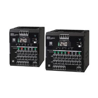
Inheriting tripping performance with the renewal, while renewing Efficiency, size, and design.
Related Contents
- Features
- Lineup
- Specifications
- Dimensions
- Catalog / Manual / CAD / Software
last update: July 1, 2026
Specifications
S8AS2-24024-06[]
| Model | S8AS2-24024-06S | S8AS2-24024-06SN | ||
|---|---|---|---|---|
| Efficiency | 100 VAC input *1 | 93% typ. (Power supply section only: 94% typ.) | ||
| 230 VAC input *1 | 95% typ. (Power supply section only: 96% typ.) | |||
| Input
conditions |
Input voltage allowable range *3 | 85 to 264 VAC | ||
| Frequency *3 | 50/60 Hz (47 to 63 Hz) | |||
| Input current | 2.6 A typ. (100 VAC input) | |||
| 1.3 A typ. (200 VAC input) | ||||
| Power factor | 0.9 or greater | |||
| Leakage current | 0.5 mA max. (100 VAC input) | |||
| 1 mA max. (200 VAC input) | ||||
| Inrush current
(for a cold start at 25°C) |
14 A typ. (100 VAC input) | |||
| 28 A typ. (200 VAC input) | ||||
| Output
characteristics |
Number of branches | 6 | ||
| Maximum cutoff
output current (per branch) |
3.8 A | |||
| Total output current | 10 A | |||
| Voltage variable range *4 | 24 to 28 V (adjustable with V.ADJ) | |||
| Ripple noise voltage
(at rated input and outputs) *1 |
80 mV max.
at 20 MHz of bandwidth |
|||
| Output leakage current | 10 mA max. | |||
| Input fluctuation | 0.5% or less (at input 85 to 264 VAC, 100% Load) *2 | |||
| Load fluctuation | 4.0% or less (at rated input, 0 to 100% Load) *2 | |||
| Ambient temperature fluctuation | 0.05%/°C max. | |||
| Startup time *5 | 1,000 ms or less *1 | |||
| Outputs hold time *5 | 30 ms typ. (at rated input and outputs) *1 | |||
| Functions | Tripping
functions |
Abnormal voltage
tripping |
26.0 to 32.0 V | 32.0 V (fixed) |
| Abnormal current
tripping *5 |
Setting range:
0.5 to 3.8 A (in 0.1 A Unit) |
3.8 A (fixed) | ||
| Abnormal current
tripping type |
Standard (default) | Extended time (Cannot be changed.) | ||
| Abnormal total
current tripping |
If a total output current equivalent to 17 A for 2 s min., 15 A for 5 s min., 13 A for 10 s min., or 12 A for 20 s min. flows, it will be interrupted. | |||
| Tripping Alarm
Output |
MOS FET relay output
30 VDC or less, 50 mA or less, leakage current 0.1 mA or less, residual voltage 2 V or less |
|||
| Undervoltage
detection functions |
Undervoltage alarm | Setting range:
18.0 to 26.4 V (in 0.1 V Unit) |
20.0 V (fixed) | |
| Undervoltage
Detection Output |
MOS FET relay output
30 VDC or less, 50mA or less, leakage current 0.1 mA or less, residual voltage 2 V or less |
|||
| Maintenance
Forecast Monitor Function |
Years up to
replacement time |
Setting range:
0.0 to 5.0 yr (in 0.1 yr Unit) |
0.5 yr (Cannot be changed.) | |
| Percentage up to
replacement time |
Setting range:
0.0 to 99.9% (in 0.1% Unit) |
0% (Cannot be changed.) | ||
| Total running time | Setting range:
0 to 132 kH (in 1 kH Unit) |
132 kHz (fixed) | ||
| Maintenance
Forecast Monitor Output |
MOS FET relay output
30 VDC or less, 50 mA or less, leakage current 0.1 mA or less, residual voltage 2 V or less |
|||
| Over-
temperature detection function |
Over-temperature | Setting range:
25 to 100°C (1°C unit) |
100°C (fixed) | |
| Over-temperature
output |
MOS FET relay output
30 VDC or less, 50 mA or less, leakage current 0.1 mA or less, residual voltage 2 V or less |
|||
| Display
functions |
Output voltage
display |
Display range: 16.3 to 32.0 V
Display accuracy: 2% rdg ±1 digit max. |
||
| Output current display | Branch output current Display range: 0.0 to 20.0 A
Branch output peak current display range: 0.0 to 20.0 A Total output current display range: 0.0 to 60.0 A Display accuracy: 5% FS (4 A) ±1 digit max. |
|||
| Maintenance
forecast monitor display (yr) |
Display range: FUL (Full) /HLF (Half) /Replacement period from 0.0 to 4.9 years | |||
| Maintenance
forecast monitor display (percentage) |
Display range: 0.0 to 99.9% | |||
| Total running time | Display range: 0 to 132 kHz | |||
| Temperature
display |
Display range: -20 to 120°C
Display accuracy: 2°C ±1 digit max. |
|||
| Additional
features |
External Tripping Input | The input can be enabled or disabled for each branch output.
19.2 to 30.0 VDC, minimum signal width: 10 ms, tripping after input within 20 ms + the shutdown sequence set time |
All branch outputs: Enabled (Cannot be changed.)
19.2 to 30.0 VDC, minimum signal width 10 ms or more, 20 ms after input |
|
| Startup sequence | Setting range:
0.0 to 99.9 seconds (0.1-second Unit) |
Branch output 1: 0.0 s (fixed)
Branch output 2: 0.4 s (fixed) Branch output 3: 0.8 s (fixed) Branch output 4: 1.2 s (fixed) Branch output 5: 1.6 s (fixed) Branch output 6: 2.0 s (fixed) |
||
| Shutdown sequence | Setting range:
0.0 to 99.9 seconds (0.1-second Unit) |
All branch outputs:
0.0 s (Cannot be changed.) |
||
| Series connection | Not supported. | |||
| Parallel connection | Not supported. | |||
| Output indicator | Provided (Color: green) | |||
| Indication
monitor |
Measurement/
displayed details |
For details, refer to S8AS2 Users Manual (Man. No. T242). | ||
| Main display area | Seven-segment display (Color: white) | |||
| Channel display
area |
Seven-segment display (Color: green) | |||
| Unit display area | Provided (Color: yellow) | |||
| Withstand
voltage |
Dielectric strength voltage | 3 kVAC for 1 min between all input terminals collectively and all branch output terminals, all I/O signal terminals collectively (Detection current: 20 mA) | ||
| 2 kVAC for 1 min between all input terminals collectively and protective earth (Detection current: 20 mA) | ||||
| 1 kVAC for 1 min between protective earth and all branch output terminals, all I/O signal terminals collectively (Detection current: 30 mA) | ||||
| 500 VAC for 1 min between all branch output terminals and all I/O signal terminals collectively (Detection current: 20 mA) | ||||
| 500 VAC for 1 min between all output signals and all input signals collectively (Detection current: 20 mA) | ||||
| Insulation resistance | 100 MΩ min. at 500 VDC between the protective earth terminal or all input terminals collectively and all branch output terminals, and all I/O signal terminals collectively | |||
| Environment | Ambient operating temperature | -25 to 70°C (with no condensation or icing) *5 | ||
| Storage temperature | -40 to 85°C | |||
| Ambient operating humidity | 95% max. | |||
| Storage humidity | 95% max. | |||
| Vibration resistance | 10 to 55 Hz, 0.375 mm single amplitude, 3 directions, 2 h each | |||
| Shock resistance | 150 m/s2 3 times each in ±X, ±Y, ±Z directions. | |||
| Reliability | MTBF | 36,000 hours min. | ||
| Expected life | 10 years | |||
| Construction | Weight (main unit) | 1,050 g max. | ||
| Cooling fan | blank | |||
| Protective structure | IP20 (Conforms to EN/IEC60529) | |||
| Compatible
standards |
Harmonic suppression | Conforms to EN61000-3-2 | ||
| EMI | Conducted EMI | Compliant with EN 61204-3 Class B, EN 55011 Class B | ||
| Radiated EMI | Compliant with EN 61204-3 Class B, EN 55011 Class B *6 | |||
| EMS | EN 61204-3 high severity levels | |||
| Safety standards *7 | UL 508 (Listing, Class 2 Output: Per UL 1310)
CSA C22.2 No.107.1 (cUL, Class 2 Output: per CSA C22.2 No.223) EN/IEC 62477-1 (SELV/ES1 Output), OVCIII (I≤2,000 m), OVCII (2,000 m< and ≤3,000 m), Pol2 Conforms to PELV (EN/IEC60204-1) Conforms to EN/IEC61558-2-16 RCM (EN61000-6-4) |
|||
| SEMI standards | Compliance with SEMI F47-0706 (for 200 to 240 VAC input) | |||
*1. Rated input/output conditions: at rated input voltage, rated frequency, rated output voltage, and rated total output current.
*2. 100% Load condition: at rated output voltage and rated total output current.
*3. Do not use an inverter output for the Power Supply. Inverters with an output frequency of 50/60 Hz are available, but the rise in the internal temperature of the Power Supply may result in ignition or burning.
Do not connect a UPS with a square wave outputs to the input. There is a risk of smoke generation and burning due to the internal temperature rise of the product.
*4. Voltage will increase above 28 V when adjusting the V.ADJ volume. When adjusting the Output voltage, please check the power supply output voltage to avoid damaging the Load. Also, when the Output voltage exceeds the Set value, all branch output will be shut off.
*5. For details, please refer to Inrush Current, Starting Time, Outputs Hold Time on Catalog.
*6. EM (I Radiated EMI) complies with Class B status this product is installed inside a Control panel.
*7. Please refer to About Compatible standards.
S8AS2-48024-08[]
| Model | S8AS2-48024-08S | S8AS2-48024-08SN | ||
|---|---|---|---|---|
| Efficiency | 100 VAC input *1 | 93% typ. (Power supply section only: 94% typ.) | ||
| 230 VAC input *1 | 95% typ. (Power supply section only: 96% typ.) | |||
| Input
conditions |
Input voltage allowable range *3 | 85 to 264 VAC | ||
| Frequency *3 | 50/60 Hz (47 to 63 Hz) | |||
| Input current | 5.2 A typ. (100 VAC input) | |||
| 2.6 A typ. (200 VAC input) | ||||
| Power factor | 0.9 min. | |||
| Leakage current | 0.5 mA max. (100 VAC input) | |||
| 1 mA max. (200 VAC input) | ||||
| Inrush current
(for a cold start at 25°C) |
14 A typ. (100 VAC input) | |||
| 28 A typ. (200 VAC input) | ||||
| Output
characteristics |
Number of branches | 8 | ||
| Maximum interrupting
Output current (per branch) |
3.8 A | |||
| Total output current | 20 A | |||
| Voltage variable range *4 | 24 to 28 V (by V.ADJ) | |||
| Ripple noise voltage
(at rated Inputs and Outputs) *1 |
190 mV or less
at 20 MHz of bandwidth |
|||
| Output leakage current | 10 mA max. | |||
| Static input fluctuation | 0.5% or less (at input 85 to 264 VAC, 100% Load) *2 | |||
| Load fluctuation | 4.0% or less (at rated input, 0 to 100% Load) *2 | |||
| Ambient temperature fluctuation | 0.05%/°C max. | |||
| Startup time *5 | 1,000 ms or less *1 | |||
| Outputs hold time *5 | 30 ms typ. (at rated Inputs and Outputs) *1 | |||
| Functions | Tripping
functions |
Abnormal voltage
tripping |
26.0 to 32.0 V | 32.0 V (fixed) |
| Abnormal current
tripping *5 |
Setting range:
0.5 to 3.8 A (in 0.1 A Unit) |
3.8 A (fixed) | ||
| Abnormal current
tripping type |
Standard (default) | Extended time (Cannot be changed.) | ||
| Abnormal total
current tripping |
The total output current equivalent to 27 A for 1 s min., 25 A for 2 s min., and 22.5 A for 5 s min. will cause disconnection. | |||
| Tripping Alarm
Output |
MOS FET relay output
30 VDC or less, 50 mA or less, leakage current 0.1 mA or less, residual voltage 2 V or less |
|||
| Undervoltage
detection functions |
Undervoltage alarm | Setting range:
18.0 to 26.4 V (in 0.1 V Unit) |
20.0 V (fixed) | |
| Undervoltage
Detection Output |
MOS FET relay output
30 VDC or less, 50 mA or less, leakage current 0.1 mA or less, residual voltage 2 V or less |
|||
| Maintenance
Forecast Monitor Function |
Years up to
replacement time |
Setting range:
0.0 to 5.0 yr (in 0.1 yr Unit) |
0.5 yr (Cannot be changed.) | |
| Percentage up to
replacement time |
Setting range:
0.0 to 99.9% (in 0.1% Unit) |
0% (Cannot be changed.) | ||
| Total running time | Setting range:
0 to 132 kHz (in 1 kHz Unit) |
132 kH (fixed) | ||
| Maintenance
Forecast Monitor Output |
MOS FET relay output
Outputs of 30 VDC or less, 50 mA or less, leakage current of 0.1 mA or less, and residual voltage of 2 V or less |
|||
| Over-
temperature detection function |
Over-temperature | Setting range:
25 to 100°C (in 1°C units) |
100°C (fixed) | |
| Over-temperature
output |
MOS FET relay output
Outputs of 30 VDC or less, 50 mA or less, leakage current of 0.1 mA or less, and residual voltage of 2 V or less |
|||
| Display
functions |
Output voltage
display |
Display range: 16.3 to 32.0 V
Display accuracy: 2% rdg ±1 digit max. |
||
| Output current
display |
Branch output current display range: 0.0 to 20.0 A
Branch output peak current display range: 0.0 to 20.0 A Total output current display range: 0.0 to 60.0 A Display accuracy: 5% FS (4 A) ±1 digit max. |
|||
| Maintenance
forecast monitor display (yr) |
Display range: FUL (Full) /HLF (Half) /0.0 to 4.9 years | |||
| Maintenance
forecast monitor display (percentage) |
Display range: 0.0 to 99.9% | |||
| Total running time | Display range: 0 to 132 kH | |||
| Temperature
display |
Display range: -20 to 120°C
Display accuracy: 2°C ±1 digit max. |
|||
| Additional
features |
External Tripping Input | The input can be enabled or disabled for each branch output.
19.2 to 30.0 VDC, minimum signal width: 10 ms, tripping after input within 20 ms + the shutdown sequence set time |
All branch outputs: Enabled (Cannot be changed.)
19.2 to 30.0 VDC, Minimum signal width: 10 ms, 20 ms after input |
|
| Startup sequence | Setting range:
0.0 to 99.9 seconds (in 0.1 second Unit) |
Branch output 1: 0.0 s (fixed)
Branch output 2: 0.4 s (fixed) Branch output 3: 0.8 s (fixed) Branch output 4: 1.2 s (fixed) Branch output 5: 1.6 s (fixed) Branch output 6: 2.0 s (fixed) Branch output 7: 2.4 s (fixed) Branch output 8: 2.8 s (fixed) |
||
| Shutdown sequence | Setting range:
0.0 to 99.9s (in 0.1s Unit) |
All branch outputs:
0.0 s (Cannot be changed.) |
||
| Series connection | Not supported. | |||
| Parallel connection | Not supported. | |||
| Output indicator | Provided (Color: green) | |||
| Indication
monitor |
Measurement/
displayed details |
For details, refer to S8AS2 Users Manual (Man. No. T242). | ||
| Main display area | Seven-segment display (Color: white) | |||
| Channel display
area |
Seven-segment display (Color: green) | |||
| Unit display area | Provided (Color: yellow) | |||
| Withstand
voltage |
Dielectric strength voltage | 3 kVAC for 1 min between all input terminals collectively and all branch output terminals, all I/O signal terminals collectively (Detection current: 20 mA) | ||
| 2 kVAC for 1 min between all input terminals collectively and protective earth (Detection current: 20 mA) | ||||
| 1 kVAC for 1 min between protective earth and all branch output terminals, all I/O signal terminals collectively (Detection current: 30 mA) | ||||
| 500 VAC for 1 min between all branch output terminals and all I/O signal terminals collectively (Detection current: 20 mA) | ||||
| 500 VAC for 1 min between all input signal collectively and all output signal collectively (Detection current: 20 mA) | ||||
| Insulation resistance | 100 MΩ min. at 500 VDC between the protective earth terminal or all input terminals collectively and all branch output terminals, and all I/O signal terminals collectively | |||
| Environment | Ambient operating temperature | -25 to 70°C (with no condensation or icing) *5 | ||
| Storage temperature | -40 to 85°C | |||
| Ambient operating humidity | 95% max. | |||
| Storage humidity | 95% max. | |||
| Vibration resistance | 10 to 55 Hz, 0.375 mm single amplitude, 3 directions, 2 h each | |||
| Shock resistance | 150 m/s2 3 times each in ±X, ±Y, ±Z directions. | |||
| Reliability | MTBF | 36,000 hours min. | ||
| Expected life | 10 years | |||
| Construction | Weight (main unit) | Less than 1,400 g | ||
| Cooling fan | blank | |||
| Protective structure | IP20 (Conforms to EN/IEC60529) | |||
| Compatible
standards |
Harmonic suppression | Conforms to EN61000-3-2 | ||
| EMI | Conducted EMI | Compliant with EN 61204-3 Class B, EN 55011 Class B | ||
| Radiated EMI | Compliant with EN 61204-3 Class B, EN 55011 Class B *6 | |||
| EMS | EN 61204-3 high severity levels | |||
| Safety standards *7 | UL 508 (Listing, Class 2 Output: Per UL 1310)
CSA C22.2 No.107.1 (cUL, Class 2 Output: per CSA C22.2 No.223) EN/IEC 62477-1 (SELV/ES1 Output), OVCIII (I≤2,000 m), OVCII (2,000 m< and ≤3,000 m), Pol2 Conforms to PELV (EN/IEC60204-1) Conforms to EN/IEC61558-2-16 RCM (EN61000-6-4) |
|||
| SEMI standards | Compliance with SEMI F47-0706 (for 200 to 240 VAC input) | |||
*1. Rated input/output conditions: at rated input voltage, rated frequency, rated output voltage, and rated total output current.
*2. 100% Load condition: at rated output voltage and rated total output current.
*3. Do not use an inverter output for the Power Supply. Inverters with an output frequency of 50/60 Hz are available, but the rise in the internal temperature of the Power Supply may result in ignition or burning.
Do not connect a UPS with a square wave outputs to the input. There is a risk of smoke generation and burning due to the internal temperature rise of the product.
*4. Voltage will increase above 28 V when adjusting the V.ADJ volume. When adjusting the Output voltage, please check the power supply output voltage to avoid damaging the Load. Also, when the Output voltage exceeds the Set value, all branch output will be shut off.
*5. For details, please refer to Inrush Current, Starting Time, Outputs Hold Time on Catalog.
*6. EM (I Radiated EMI) complies with Class B status this product is installed inside a Control panel.
*7. Please refer to About Compatible standards below.
About Compatible standards
• Regarding EN/IEC 61558-2-16
When acquiring EN/IEC 60204-1 (Machinery Safety), control circuits require a control transformer; however, products that have obtained safety standards with OVCIII or products adopting transformers compliant with EN/IEC 61558-2-16 may not require a control transformer.
[The processes and costs for the UL certificate can be reduced.] UL Class2
What is the UL Class 2 output?
It is the classification that indicates “power supplies and the related products with safety outputs of which voltage, current, and power are limited to a certain level, so that not to cause an electric shock or fire,” and is evaluated by UL1310.
For the UL Class 2 output, the voltage, current, and power are provided as follows:
• DC30 V or lower of output voltage
• 8 A or lower of output current
• 100 VA or lower of output power
Any loads and parts to be connected to this UL Class 2 output can be used without UL certificate.
What is the UL Class 2 output in the S8AS2 series
To meet the conditions of this UL Class 2 output, the maximum output current per output branch is fixed at 3.8 A.
• 24 V of output voltage → meets DC30 V or lower
• 3.8 A of output current → meets 8 A or lower
• 24 V * 3.8 A of output power = 91.2 VA → meets 100 VA or lower
The processes and costs for applying to a safety standard for the devices can be reduced.
As the S8AS2 series have already certified the UL Class 2 output, the UL evaluation of the circuit to be connected to this output may not be needed, which can help reduce processes and costs for the UL certificate. Any loads and parts to be connected to this UL Class 2 output can be used without UL certificate.
Furthermore, that also helps for cost down and easy selection of the parts, because any wiring materials without UL certificate are usable in the control panel.
last update: July 1, 2026