H3DT-A
Power ON-delay Timer
Our Value Design Products Increase the Value of Your Control Panels. Single Mode Timers with power ON delay operation.
Related Contents

- Features
- Lineup
- Specifications
- Dimensions
- Catalog / Manual / CAD / Software
last update: July 19, 2021
Time Ranges
| Time range setting | 0.1 s | 1 s | 10 s | 1 min | 10 min | 1 h | 10 h | 100 h |
|---|---|---|---|---|---|---|---|---|
| Set time range | 0.1 to 1.2 s | 1 to 12 s | 10 to 120 s | 1 to 12 min | 10 to
120 min |
1 to 12 h | 10 to 120 h | 100 to
1,200 h |
| Scale numbers | 12 | |||||||
Ratings
| Power supply voltage *1 | 24 to 240 VAC/DC, 50/60 Hz *2 | |
|---|---|---|
| Allowable voltage fluctuation
range |
85% to 110% of rated voltage | |
| Power reset | Minimum power-OFF time: 0.1 s | |
| Reset voltage | 10% of rated voltage | |
| *3
Power consumption |
H3DT-A2 | At 240 VAC: 2.2 VA max., at 240 VDC: 0.7 W max.,
at 24 VDC: 0.3 W max. |
| H3DT-A1 | At 240 VAC: 1.8 VA max., at 240 VDC: 0.6 W max.,
at 24 VDC: 0.3 W max. |
|
| Rated Insulation Voltage | 250 VAC | |
| Control output | Contact output:
5 A at 250 VAC with resistive load (cosφ = 1), 5 A at 30 VDC with resistive load, 0.15 A max. at 125 VDC with resistive load, 0.1A max. at 125 VDC with L/R of 7 ms. The minimum applicable load is 10 mA at 5 VDC (P reference value). Contact materials: Ag-alloy (Recommended fuse: BLN5 (Littelfuse) or 0216005MXEP) |
|
| Ambient operating
temperature |
-20 to 60°C (with no icing) | |
| Storage temperature | -40 to 70°C (with no icing) | |
| Surrounding air operating
humidity |
25% to 85% | |
*1. When using a 24-VDC power supply voltage, there will be an inrush current of approximately 0.5 A.
Allow for this inrush current when turning ON and OFF the power supply to the Timer with device with a solid-state output,
such as a sensor.
*2. DC ripple: 20% max.
*3. The power consumption is the value after the Timer times out.
Characteristics
| Accuracy of operating
time |
±1% of FS max. (±1% ±10 ms max. at 1.2-s range) | |
|---|---|---|
| Setting error | ±10% of FS ±0.05 s max. | |
| Influence of voltage | ±0.5% of FS max. (±0.5% ±10 ms max. at 1.2-s range) | |
| Influence of
temperature |
±2% of FS max. (±2% ±10 ms max. at 1.2-s range) | |
| Insulation resistance | 100 MΩ min. at 500 VDC | |
| Dielectric strength | Between charged metal part and operating section:
2,900 VAC 50/60 Hz for 1 min. Between control output terminals and operating circuit: 2,000 VAC 50/60 Hz for 1 min. Between contacts not located next to each other: 1,000 VAC 50/60 Hz for 1 min. |
|
| Impulse withstand
test voltage |
5 kV between power terminals,
7.4 kV between conductor terminal and operating section |
|
| Noise immunity | Square-wave noise generated by noise simulator
(pulse width: 100 ns/1 μs, 1-ns rise): ±1.5 kV |
|
| Static immunity | Malfunction: 4 kV, Destruction: 8 kV | |
| Vibration
resistance |
Destruction | 0.75-mm single amplitude at 10 to 55 Hz for 2 h each in 3 directions |
| Malfunction | 0.5-mm single amplitude at 10 to 55 Hz for 10 min each in 3 directions | |
| Shock
resistance |
Destruction | 1,000 m/s2 3 times each in 6 directions |
| Malfunction | 100 m/s2 3 times each in 6 directions | |
| Life
expectancy |
Mechanical | 10 million operations min. (under no load at 1,800 operations/h) |
| Electrical | 100,000 operations min. (5 A at 250 VAC, resistive load at 360 operations/h) | |
| Degree of protection | IP30 (Terminal block: IP20) | |
| Weight | Approx. 100 g | |
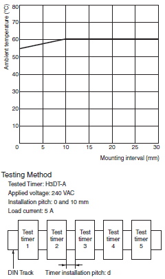
Relation between H3DT Ambient Temperature and Mounting Interval (Reference Values)
The relation between the ambient temperature and mounting interval is shown in the following graph.
If the Timer is used at 55°C or higher with a mounting interval that is smaller than that shown in the following diagram, the temperature inside the Timer will increase, reducing the life expectancy of internal parts.
Applicable standards
| Safety standards | cULus: UL 508/CSA C22.2 No. 14
EN 61812-1: Pollution degree 2, Overvoltage category III CCC: GB/T 14048.5 Pollution degree 2, Overvoltage category III * LR: Category ENV1.2 |
|---|---|
| EMC | (EMI) EN 61812-1
Radiated Emissions: EN 55011 class B Emission AC Mains: EN 55011 class B Harmonic Current: EN 61000-3-2 Voltage Fluctuations and Flicker: EN 61000-3-3 (EMS) EN 61812-1 Immunity ESD: EN 61000-4-2 Immunity RF-interference: EN 61000-4-3 Immunity Burst: EN 61000-4-4 Immunity Surge: EN 61000-4-5 Immunity Conducted Disturbance: EN 61000-4-6 Immunity Voltage Dip/Interruption: EN 61000-4-11 |
* CCC certification requirements
| Rated operating voltage Ue
Rated operating current Ie |
AC-15: Ue: 250 VAC, Ie: 3 A
AC-13: Ue: 250 VAC, Ie: 5 A DC-13: Ue: 30 VDC, Ie: 0.1 A |
|---|---|
| Rated impulse withstand voltage
(altitude: 2,000 m max.) |
4 kV (at 240 VAC) |
| Conditional short-circuit current | 1,000 A |
I/O
| Input | None | |
|---|---|---|
| Output | Control output | The output is turned ON/OFF according to the operating mode when the value that is set on
the dial is reached. |
last update: July 19, 2021