S8VK-S
S8VK-S (30/60/120/240/480-W Models)
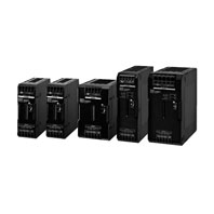
A Perfect Fit for Small Control Panels Coated PCBs for Better Resistance to Environment Connections for Easy Wiring
Related Contents

- Features
- Lineup
- Specifications
- Dimensions
- Catalog / Manual / CAD / Software
last update: July 8, 2024
Ratings, Characteristics, and Functions
| Power rating | 30 W | 60 W | 120 W | ||
|---|---|---|---|---|---|
| Output voltagec (DC) | 24 V | 24 V | 24 V | ||
| Efficiency | 115 VAC input *1 | 87% typ. | 87% typ. | 90% typ. | |
| 230 VAC input *1 | 86% typ. | 89% typ. | 92% typ. | ||
| Input | Voltage range *2 | Single-phase, 85 to 264 VAC, 90 to 350 VDC *12,
265 to 300 VAC (1 second) |
|||
| Frequency *2 | 50/60 Hz (47 to 450 Hz) | 50/60 Hz (47 to 63
Hz) |
|||
| Input current | 115 VAC input *1 | 0.58A typ. | 1.1 A typ. | 1.2 A typ. | |
| 230 VAC input *1 | 0.36A typ. | 0.66 A typ. | 0.63 A typ. | ||
| Power factor *1 | --- | 0.9 min. | |||
| Leakage
current *3 |
115 VAC input | 0.5 mA max. | |||
| 230 VAC input | 1 mA max. | ||||
| Inrush current
*4 (for a cold start at 25°C) |
115 VAC input | 16 A typ. | |||
| 230 VAC input | 32 A typ. | ||||
| Output | Rated output current | 1.3 A | 2.5 A | 5 A | |
| Rated output electric power | 31.2 W | 60 W | 120 W | ||
| Maximum boost current | 1.56 A | 3 A | 6 A | ||
| Voltage adjustment range *5 | 21.6 to 28 V (with V.DJ) | ||||
| Ripple & Noise
voltage *6 |
100 to 240 VAC
input *1 |
190 mVp-p max. at
20 MHz of bandwidth |
190 mVp-p max. at
20 MHz of bandwidth |
110 mVp-p max. at
20 MHz of bandwidth |
|
| Input variation influence *7 | 0.5% max. | ||||
| Load variation influence *8 | 1.5% max. | ||||
| Temperature
variation influence |
115 to 230 VAC
input |
0.05%/°C max. | |||
| Start up time
*4 |
115 VAC input *1 | 1000 ms max. | 1000 ms max. | 1000 ms max. | |
| 230 VAC input *1 | 1000 ms max. | 1000 ms max. | 1000 ms max. | ||
| Hold time *6 | 115 VAC input *1 | 30 ms typ. | 20 ms typ. | 45 ms typ. | |
| 230 VAC input *1 | 140 ms typ. | 95 ms typ. | 45 ms typ. | ||
| Additional
functions |
Overload protection | Yes, automatic reset | |||
| Overvoltage protection *9 | Yes, 130% or higher of rated output voltage, power shut off (shut
off the input voltage and turn on the input again) |
||||
| Series operation | Yes (For up to two Power Supplies, external diodes are required.) | ||||
| Parallel operation | Yes (For up to two Power Supplies), Refer to Parallel Operation on
catalog for details. |
||||
| Output indicator | Yes (LED: Green) | ||||
| Low-voltage detection output | No | ||||
| Insulation | Withstand voltage | 3.0 kVAC for 1 min. (between all input terminals and output
terminals), current cutoff 10 mA |
|||
| 2.0 kVAC for 1 min. (between all input terminals and PE terminals),
current cutoff 10 mA |
|||||
| 1.0 kVAC for 1 min. (between all output terminals and PE terminals),
current cutoff 20 mA |
|||||
| Insulation resistance | 100 MΩ min. (between all output terminals and all input terminals/
PE terminals) at 500 VDC |
||||
| Environ-
ment |
Ambient operating temperature
*10 |
-40 to 70°C (Derating is required according to the temperature.
Refer to Engineering Data) (with no condensation or icing) |
|||
| Storage temperature | -40 to 85°C (with no condensation or icing) | ||||
| Ambient operating humidity | 95% RH max. (Storage humidity: 95% RH max.) | ||||
| Vibration resistance | 10 to 55 Hz, maximum 5G, 0.42 mm half amplitude for 2 h each in
X, Y, and Z directions |
||||
| Shock resistance | 150 m/s2, 3 times each in ±X, ±Y, ±Z directions | ||||
| Reliability | MTBF | 135,000 hrs min. (Refer to Data Sheet Reference Value) | |||
| Life expectancy *11 | 10 years min. | ||||
| Con-
struction |
Weight | 250 g max. | 250 g max. | 400 g max. | |
| Cooling fan | No | ||||
| Degree of protection | IP20 by EN/IEC 60529 | ||||
| Standards | Harmonic current emissions | Conforms to EN 61000-3-2 | |||
| EMI | Conducted
Emissions |
Conforms to EN 61204-3 Class B, EN 55011 Class B | |||
| Radiated
Emissions |
Conforms to EN 61204-3 Class B, EN 55011 Class B | ||||
| EMS | Conforms to EN 61204-3 high severity levels | ||||
| Safety standards | UL Listing: UL 508 (For 30 W and 60 W only Class2 Output: Per UL 1310)
cUL: CSA C22.2 No107.1 (For 30 W and 60 W only Class2 Output: Per CSA C22.2 No.223) UL UR: UL 62368-1 (Recognition) OVCII (≤ 3000 m) Pol2 cUR: CSA C22.2 No. 62368-1 OVCII (≤ 3000 m) Pol2 EN: EN 62477-1 OVCIII (≤ 2000 m) OVCII (2000 m≤ and≤3000) Pol2, EN 62368-1 OVCII (≤ 3000 m) Pol2 RCM (EN61000-6-4) PELV (EN/IEC 60204-1) *12 EN/IEC 61558-2-16:2009+A1:2013 *12 BIS: IS 13252 (Part1) (Except 30 W) *12 |
||||
| Marine Standards *12 | Lloyd’s register (Except 30 W) | ||||
| SEMI | Conforms to F47-0706 (200 to 240 VAC input) | ||||
| Power rating | 240 W | 480 W | ||
|---|---|---|---|---|
| Output voltagec (DC) | 24 V | 24 V | ||
| Efficiency | 115 VAC input *1 | 91% typ. | 91% typ. | |
| 230 VAC input *1 | 93% typ. | 93% typ. | ||
| Input | Voltage range *2 | Single-phase, 85 to 264 VAC, 90 to 350 VDC *12, 265 to 300 VAC
(1 second) |
||
| Frequency *2 | 50/60 Hz (47 to 63 Hz) | |||
| Input current | 115 VAC input *1 | 2.4 A typ. | 4.6 A typ. | |
| 230 VAC input *1 | 1.3 A typ. | 2.3 A typ. | ||
| Power factor *1 | 0.9 min. | 0.9 min. | ||
| Leakage
current *3 |
115 VAC input | 0.5 mA max. | ||
| 230 VAC input | 1 mA max. | |||
| Inrush current
*4 (for a cold start at 25°C) |
115 VAC input | 16 A typ. | ||
| 230 VAC input | 32 A typ. | |||
| Output | Rated output current | 10 A | 20 A | |
| Rated output electric power | 240 W | 480 W | ||
| Maximum boost current | 15 A | 30 A | ||
| Voltage adjustment range *5 | 21.6 to 28 V (with V.ADJ) | |||
| Ripple & Noise
voltage *6 |
100 to 240 VAC
input *1 |
100 mVp-p max.
at 20 MHz of bandwidth |
130 mVp-p max.
at 20 MHz of bandwidth |
|
| Input variation influence *7 | 0.5% max. | |||
| Load variation influence *8 | 1.5% max. | |||
| Temperature
variation influence |
115 to 230 VAC
input |
0.05%/°C max. | ||
| Start up time
*4 |
115 VAC input *1 | 1000 ms max. | 1000 ms max. | |
| 230 VAC input *1 | 1000 ms max. | 1000 ms max. | ||
| Hold time *6 | 115 VAC input *1 | 35 ms typ. | 30 ms typ. | |
| 230 VAC input *1 | 35 ms typ. | 30 ms typ. | ||
| Additional
functions |
Overload protection | Yes, automatic reset | ||
| Overvoltage protection *9 | Yes, 130% or higher of rated output voltage, power shut off (shut
off the input voltage and turn on the input again) |
|||
| Series operation | Yes (For up to two Power Supplies, external diodes are required.) | |||
| Parallel operation | Yes (For up to two Power Supplies), Refer to Parallel Operation on
catalog for details. |
|||
| Output indicator | Yes (LED: Green) | |||
| Low-voltage detection output | Yes (Photoswitch output: 30 VDC max., 50 mA max.) | |||
| Insulation | Withstand voltage | 3.0 kVAC for 1 min. (between all input terminals and output
terminals), current cutoff 20 mA |
||
| 2.0 kVAC for 1 min. (between all input terminals and PE terminals),
current cutoff 20 mA |
||||
| 1.0 kVAC for 1 min. (between all output terminals and PE terminals),
current cutoff 20 mA |
||||
| 500 VAC for 1 min (between all output terminals and all low-voltage
detection output terminals), current cutoff 10 mA |
||||
| Insulation resistance | 100 MΩ min. (between all output terminals/all low-voltage
detection output terminals and all input terminals/PE terminals) at 500 VDC |
|||
| Environ-
ment |
Ambient operating temperature
*10 |
-40 to 70°C (Derating is required according to the temperature.
Refer to Engineering Data) (with no condensation or icing) |
||
| Storage temperature | -40 to 85°C (with no condensation or icing) | |||
| Ambient operating humidity | 95% RH max. (Storage humidity: 95% RH max.) | |||
| Vibration resistance | 10 to 55 Hz, maximum 5G, 0.42 mm half amplitude for 2 h each in
X, Y, and Z directions |
|||
| Shock resistance | 150 m/s2, 3 times each in ±X, ±Y, ±Z directions | |||
| Reliability | MTBF | 135,000 hrs min. (Refer to Data Sheet Reference Value) | ||
| Life expectancy *11 | 10 years min. | |||
| Con-
struction |
Weight | 700 g max. | 1150 g max. | |
| Cooling fan | No | |||
| Degree of protection | IP20 by EN/IEC 60529 | |||
| Standards | Harmonic current emissions | Conforms to EN 61000-3-2 | ||
| EMI | Conducted
Emissions |
Conforms to EN 61204-3 Class B, EN 55011 Class B | ||
| Radiated
Emissions |
Conforms to EN 61204-3 Class B, EN 55011 Class B | |||
| EMS | Conforms to EN 61204-3 high severity levels | |||
| Safety standards | UL Listing: UL 508
cUL: CSA C22.2 No107.1 UL UR: UL 62368-1 (Recognition) OVCII (≤ 3000 m) Pol2 cUR: CSA C22.2 No.62368-1 OVCII (≤ 3000 m) Pol2 EN: EN 62477-1 OVCIII (≤ 2000 m) OVCII (2000 m≤ and≤3000) Pol2, EN 62368-1 OVCII (≤ 3000 m) Pol2 PELV (EN/IEC 60204-1) *12 EN/IEC 61558-2-16:2009+A1:2013 *12 BIS: IS 13252 (Part1) *12 |
|||
| Marine Standards *12 | Lloyd's register | |||
| SEMI | Conforms to F47-0706 (200 to 240 VAC input) | |||
*1. The value is when both rated output voltage and rated output current are satisfied.
*2. Do not use an inverter output for the product. Inverters with an output frequency of 50/60 Hz are available, but the rise
in the internal temperature of the product may result in ignition or burning.
If the input is connected to a UPS, do not connect a UPS with a square-wave output.
Doing so will cause the internal temperature of the product to increase, possibly causing smoking or burning.
*3. The value for the leakage current is determined according to the Electrical Appliances and Material Safety Act.
*4. Refer to Inrush Current, Startup Time, Output Hold Time on Catalog for details.
*5. If the output voltage adjuster (V. ADJ) is turned, the voltage will increase by more than 28 V min of the voltage
adjustment range. When adjusting the output voltage, confirm the actual output voltage from the product and be sure
that the load is not damaged.
*6. A characteristic when the ambient operating temperature of 25°C.
*7. This is the maximum variation in the output voltage when the input voltage is gradually changed within the allowable
input voltage range at the rated output voltage and rated output current.
*8. 100 to 240 VAC input, in the range of 0 A to the rated output current.
*9. Refer to Overvoltage Protection on Catalog for the time when input voltage shuts off and input turns on again.
*10.At -40 to -25°C, time will be required before the rated output voltage is output after the input voltage is input.
Also, the ripple noise value may exceed the value shown in the above table.
*11.Refer to Recommended Replacement Periods and Periodic Replacement for Preventive Maintenance on Catalog
for details.
*12.Refer to Standard Compliance, below.
Standard Compliance
• EN/IEC 61558-2-16
The S8VK-S was designed based on EN/IEC 61558-2-16.
Currently, IEC 61558-2-17 has been replaced by IEC 61558-2-16.
When certification was received for EN/IEC 60204-1 (Machinery Safety), it was necessary to go through a control
transformer to the control circuits. However, a control transformer is not always necessary for product that have been
certified for the safety standard for OVCIII or for product that use a transformer that conforms to EN/IEC 61558-2-16.
• Safety Standards for a DC Input
The following safety standards are applicable for when a DC input is used: UL 62368-1, cUR (CSA C22.2 No. 62368-1),
EN 50178, EN 62368-1 and Lloyd's.
Safety standard compliance is achievable by connecting a UL-certified fuse as specified below.
Select an external fuse that satisfies the following conditions:
S8VK-S03024: 350 VDC min., 6 A
S8VK-S06024: 350 VDC min., 6 A
S8VK-S12024: 350 VDC min., 8 A
S8VK-S24024: 350 VDC min., 8 A
S8VK-S48024: 350 VDC min., 12 A
• Conformance to Marine Standards
Noise filter “FN2080-10-06” manufactured by SCHAFFNER Corporation. or equivalent should be connected to the Input
terminals of S8VK-S series (Except 60 W).
End Plate (PFP-M) to both sides of the Power Supply to hold the Power Supply in place.
Install clamp filters (“ZCAT2035-0930” manufactured by TDK) on the cables connected to the input and output terminals
for 240- and 480-W models.
• To comply with PELV output requirements for EN/IEC 60204-1, ground the negative side of the output (-V) to a protective
earth (PE).
• This BIS Standard is an Indian standard that has been in effect for this product since April 2021, and certification has
been acquired for 60 W, 120 W, 240 W, and 480 W models to enable individual product export to India.
last update: July 8, 2024