Discontinued On Apr. 2025
F3W-MA
Smart Muting Actuator
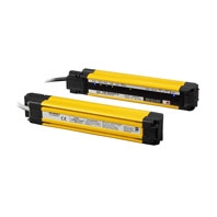
Integrated muting sensor based on multi-beam photoelectric sensor
* Information in this page is a reference that you created on the basis of information in the product catalog before the end of production, may be different from the current situation, such as goods for / supported standards options / price / features of the product. Before using, please check the compatibility and safety system.
Related Contents

- Features
- Lineup
- Specifications
- Dimensions
- Catalog / Manual / CAD / Software
last update: December 9, 2021
Ratings/Specifications
| F3W-MA0100P | F3W-MA0300P | |||
|---|---|---|---|---|
| Perfor-
mance |
Beam Gap between Muting
Trigger Beams |
100 mm | 300 mm | |
| Number of Beams | 8 | 20 | ||
| Standard Detection Object | 30 mm | |||
| Operating
Range |
Long | 0.3 to 20.0 m (1 to 65 ft.) | ||
| Short | 0.3 to 7.0 m (1 to 23 ft.) | |||
| Response
Time |
Operation | 13 ms max. | ||
| Reset | 26 ms max. (Synchronized)
78 ms max. (Not synchronized) |
|||
| Effective Aperture Angle | ±2.5° max., emitter and receiver at operating range of 3 m or greater | |||
| Light Source | Infrared LEDs, Wavelength: 870 nm | |||
| Startup Waiting Time | 2 s max. | |||
| Elec-
trical |
Power Supply Voltage (Vs) | SELV/PELV 24 VDC±20% (ripple p-p 10% max.) | ||
| Current
Consumption |
Emitter | 35 mA | 45 mA | |
| Receiver | 75 mA | 75 mA | ||
| Muting Outputs | Two PNP transistor outputs. *
Load current of 300 mA max., Residual voltage of 2 V max. (except for voltage drop due to cable extension) |
|||
| * This product is a PNP output model. Use with the PNP output model safety light curtain. | ||||
| Output
Operation Mode |
Muting
Output A |
Dark-ON
(Muting Output A is enabled when MUTE A trigger beam is blocked.) |
||
| Muting
Output B |
Dark-ON
(Muting Output B is enabled when MUTE B trigger beam is blocked.) |
|||
| Input
Voltage |
ON Voltage | [MUTE Enable]
Vs to Vs-3 V (sink current 5 mA max.) * |
||
| OFF Voltage | [MUTE Enable]
0 to 1/2 Vs, or open * |
|||
| * The Vs indicates a supply voltage value in your environment. | ||||
| Indicators | Refer to "LED Indicator Status". | |||
| Protective Circuit | Protective Circuit Output short protection, Power supply reverse polarity protection | |||
| Insulation Resistance | 20 MΩ or higher (500 VDC megger) | |||
| Dielectric Strength | 1,000 VAC, 50/60 Hz (1 min) | |||
| Func-
tional |
Functions | - Scan Code Selection
- Operation Mode Selection (Point to Point Detection/Chattering and Void Space Prevention) - Off-Delay - Muting Enable - Muting Trigger Beam Allocation - Operating Range Selection |
||
| Environ-
mental |
Ambient
Temperature |
Operating | -10 to 55°C (13 to 131°F) (non-icing) | |
| Storage | -25 to 70°C (-13 to 158°F) | |||
| Ambient
Humidity |
Operating | 35% to 85% (non-condensing) | ||
| Storage | 35% to 95% | |||
| Ambient Illuminance | Incandescent lamp: 3,000 Ix max. on receiver surface
Sunlight: 10,000 Ix max. on receiver surface |
|||
| Degree of Protection
(IEC 60529) |
IP65 and IP67 | |||
| Vibration Resistance
(IEC 61496-1) |
10 to 55 Hz, Multiple amplitude of 0.7 mm, 20 sweeps for all 3 axes | |||
| Shock Resistance
(IEC 61496-1) |
100 m/s2, 1000 shocks for all 3 axes | |||
| Pollution Degree
(IEC 60664-1) |
Pollution Degree 3 | |||
| Connec-
tions |
Power Cable | Type of
Connection |
M12 connectors: 5-pin emitter, 8-pin receiver, IP67 rated when mated, Cables prewired to sensors | |
| Number of
Wires |
Emitter: 5, Receiver: 8 | |||
| Cable
Length |
0.3 mm | |||
| Cable
Diameter |
6 mm | |||
| Minimum
Bending Radius |
R5 mm | |||
| Extension of Power Cable | 100 m max.
Note: For T-Shaped configuration with COM lines, the length of cable extension is 30 m max. |
|||
| Material | Housing: Aluminum alloy, Cap: PBT resin, Front window: Acrylic resin, Cable: Oil-resistant PVC resin, FE plate: Stainless steel | |||
| Net Weight *1 | 0.7 kg | 0.9 kg | ||
| Gross Weight *2 | 1.3 kg | 2.2 kg | ||
| Included Accessories | Instruction Sheet | |||
*1. The net weight is the weight of an emitter and a receiver.
*2. The gross weight is the weight of an emitter, a receiver, included accessories and a package.
LED Indicator Status
Shown below are indication statuses of F3W-MA LED indicators when you purchased.
Emitter
| Name of Indicator | Color | Illuminated | Blinking | |
|---|---|---|---|---|
| Operating range | LONG | Green | Long Range mode is selected by
DIP Switch. |
- |
| Running | RUN | Green | Power is ON. | - |
| Error | ERR | Red | - | Error in emitter. Generic error happens. |
Receiver
| Name of Indicator | Color | Illuminated | Blinking | |
|---|---|---|---|---|
| Top-beam-state | TOP | Blue | The top beam is unblocked. | - |
| Muting output A | MUTE A | Green | Muting Output A is activated. | - |
| Muting output B | MUTE B | Green | Muting Output B is activated. | - |
| Off-Delay | DELAY | Yellow | Off-Delay function is enabled by DIP
Switch. |
- |
| Chattering/
Void space |
CHAT | Green | Chattering and Void Space
Prevention mode is selected by DIP Switch. |
- |
| Muting Enable | MUTE
DISABLE |
Red | The Muting Enable function is
enabled and Muting Enable input is turned OFF by DIP Switch. |
- |
| Error | ERR | Red | - | Error in receiver. Generic error happens. |
| Stable-state | STB | Green | Incident light level is 170% or higher
of ON-threshold |
- |
| Running | RUN | Green | Power is ON. | - |
| Communication | COM | Green | Synchronization between emitter
and receiver is maintained. |
Primary sensor]
- Start-up (for approx. 3 s) - Synchronization between emitter and receiver is lost |
| Bottom-beamstate | BTM | Blue | The bottom beam is unblocked. | - |
last update: December 9, 2021