NX-OD / OC
NX-series Digital Output Units
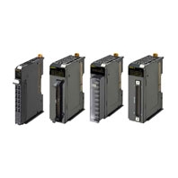
A Wide Range of Digital Output Units from General Purpose use to High- Speed Synchronous Control
Related Contents
- Features
- Lineup
- Specifications
- Dimensions
- Catalog / Manual / CAD / Software
last update: October 11, 2016
General Specification
| Item | Specification | |
|---|---|---|
| Enclosure | Mounted in a panel | |
| Grounding method | Ground to 100 Ω or less | |
| Operating
environment |
Ambient operating temperature | 0 to 55°C |
| Ambient operating humidity | 10% to 95% (with no condensation or icing) | |
| Atmosphere | Must be free from corrosive gases. | |
| Ambient storage temperature | -25 to 70°C (with no condensation or icing) | |
| Altitude | 2,000 m max. | |
| Pollution degree | 2 or less: Conforms to JIS B3502 and IEC 61131-2. | |
| Noise immunity | 2 kV on power supply line (Conforms to IEC61000-4-4.) | |
| Overvoltage category | Category II: Conforms to JIS B3502 and IEC 61131-2. | |
| EMC immunity level | Zone B | |
| Vibration resistance *1 | Conforms to IEC 60068-2-6.
5 to 8.4 Hz with 3.5-mm amplitude, 8.4 to 150 Hz, acceleration of 9.8 m/s2, 100 min each in X, Y, and Z directions (10 sweeps of 10 min each = 100 min total) |
|
| Shock resistance *1 | Conforms to IEC 60068-2-27. 147 m/s2, 3 times each in X, Y, and
Z directions |
|
| Applicable standards *2 | cULus: Listed (UL508) or Listed (UL 61010-2-201),
ANSI/ISA 12.12.01, EU: EN 61131-2 or EN 61010-2-201, C-Tick or RCM, KC: KC Registration, NK, LR |
|
*1 For the Relay Output Unit, refer to the Digital Input Unit Specifications.
*2 Refer to the OMRON website (http://www.ia.omron.com/support/models/index.html) or consult your OMRON
representative for the most recent applicable standards for each model.
*2 Refer to the OMRON website (http://www.ia.omron.com/support/models/index.html) or consult your OMRON
representative for the most recent applicable standards for each model.
Digital Output Unit Specifications
Transistor Output Unit (Screwless Clamping Terminal Block 12 mm, Width)
NX-OD2154
| Unit name | Transistor Output Unit | Model | NX-OD2154 |
|---|---|---|---|
| Number of points | 2 points | External connection
terminals |
Screwless clamping terminal block
(8 terminals) |
| I/O refreshing
method |
Output refreshing with specified time stamp | ||
| Indicators | TS indicator,
output indicator  |
Internal I/O common | NPN |
| Rated voltage | 24 VDC | ||
| Operating load
voltage range |
15 to 28.8 VDC | ||
| Maximum value of
load current |
0.5 A/point, 1 A/Unit | ||
| Maximum inrush
current |
4.0 A/point, 10 ms max. | ||
| Leakage current | 0.1 mA max. | ||
| Residual voltage | 1.5 V max. | ||
| ON/OFF response
time |
300 ns max./300 ns max. | ||
| Dimensions | 12 (W) x 100 (H) x 71 (D) | Isolation method | Digital isolator isolation |
| Insulation
resistance |
20 MΩ min. between isolated
circuits (at 100 VDC) |
Dielectric strength | 510 VAC between isolated circuits for
1 minute at a leakage current of 5 mA max. |
| I/O power supply
method |
Supply from the NX bus | Current capacity of
I/O power supply terminal |
IOV: 0.5 A/terminal max.,
IOG: 0.5 A/terminal max. |
| NX Unit power
consumption |
• Connected to a CPU Unit
0.85 W max. • Connected to a Communications Coupler Unit 0.45 W max. |
I/O current
consumption |
30 mA max. |
| Weight | 70 g max. | ||
| Circuit layout |
 This unit uses a push-pull output circuit. |
||
| Installation
orientation and restrictions |
Installation orientation:
• Connected to a CPU Unit: Possible in upright installation. • Connected to a Communications Coupler Unit: Possible in 6 orientations. Restrictions: No restrictions |
||
| Terminal
connection diagram |
 |
||
| Disconnection/
Short-circuit detection |
Not supported. | Protective function | Not supported. |
NX-OD2258
| Unit name | Transistor Output Unit | Model | NX-OD2258 |
|---|---|---|---|
| Number of points | 2 points | External connection
terminals |
Screwless clamping terminal block
(8 terminals) |
| I/O refreshing
method |
Output refreshing with specified time stamp | ||
| Indicators | TS indicator,
output indicator  |
Internal I/O common | PNP |
| Rated voltage | 24 VDC | ||
| Operating load
voltage range |
15 to 28.8 VDC | ||
| Maximum value of
load current |
0.5 A/point, 1 A/Unit | ||
| Maximum inrush
current |
4.0 A/point, 10 ms max. | ||
| Leakage current | 0.1 mA max. | ||
| Residual voltage | 1.5 V max. | ||
| ON/OFF response
time |
300 ns max./300 ns max. | ||
| Dimensions | 12 (W) x 100 (H) x 71 (D) | Isolation method | Digital isolator isolation |
| Insulation
resistance |
20 MΩ min. between isolated
circuits (at 100 VDC) |
Dielectric strength | 510 VAC between isolated circuits for
1 minute at a leakage current of 5 mA max. |
| I/O power supply
method |
Supply from the NX bus | Current capacity of
I/O power supply terminal |
IOV: 0.5 A/terminal max.,
IOG: 0.5 A/terminal max. |
| NX Unit power
consumption |
• Connected to a CPU Unit
0.85 W max. • Connected to a Communications Coupler Unit 0.50 W max. |
I/O current
consumption |
40 mA max. |
| Weight | 70 g max. | ||
| Circuit layout |
 This unit uses a push-pull output circuit. |
||
| Installation
orientation and restrictions |
Installation orientation:
• Connected to a CPU Unit: Possible in upright installation. • Connected to a Communications Coupler Unit: Possible in 6 orientations. Restrictions: No restrictions |
||
| Terminal
connection diagram |
 |
||
| Disconnection/
Short-circuit detection |
Not supported. | Protective function | With load short-circuit protection. |
NX-OD3121
| Unit name | Transistor Output Unit | Model | NX-OD3121 |
|---|---|---|---|
| Number of points | 4 points | External connection
terminals |
Screwless clamping terminal block (12
terminals) |
| I/O refreshing
method |
Selectable Synchronous I/O refreshing or Free-Run refreshing | ||
| Indicators | TS indicator,
output indicator  |
Internal I/O common | NPN |
| Rated voltage | 12 to 24 VDC | ||
| Operating load
voltage range |
10.2 to 28.8 VDC | ||
| Maximum value of
load current |
0.5 A/point, 2 A/Unit | ||
| Maximum inrush
current |
4.0 A/point, 10 ms max. | ||
| Leakage current | 0.1 mA max. | ||
| Residual voltage | 1.5 V max. | ||
| ON/OFF response
time |
0.1 ms max./0.8 ms max. | ||
| Dimensions | 12 (W) x 100 (H) x 71 (D) | Isolation method | Photocoupler isolation |
| Insulation
resistance |
20 MΩ min. between isolated
circuits (at 100 VDC) |
Dielectric strength | 510 VAC between isolated circuits for
1 minute at a leakage current of 5 mA max. |
| I/O power supply
method |
Supply from the NX bus | Current capacity of
I/O power supply terminal |
IOV: 0.5 A/terminal max.,
IOG: 0.5 A/terminal max. |
| NX Unit power
consumption |
• Connected to a CPU Unit
0.90 W max. • Connected to a Communications Coupler Unit 0.55 W max. |
I/O current
consumption |
10 mA max. |
| Weight | 70 g max. | ||
| Circuit layout |  |
||
| Installation
orientation and restrictions |
Installation orientation:
• Connected to a CPU Unit: Possible in upright installation. • Connected to a Communications Coupler Unit: Possible in 6 orientations. Restrictions: No restrictions |
||
| Terminal
connection diagram |
 |
||
| Disconnection/
Short-circuit detection |
Not supported. | Protective function | Not supported. |
NX-OD3153
| Unit name | Transistor Output Unit | Model | NX-OD3153 |
|---|---|---|---|
| Number of points | 4 points | External connection
terminals |
Screwless clamping terminal block (12
terminals) |
| I/O refreshing
method |
Selectable Synchronous I/O refreshing or Free-Run refreshing | ||
| Indicators | TS indicator,
output indicator  |
Internal I/O common | NPN |
| Rated voltage | 24 VDC | ||
| Operating load
voltage range |
15 to 28.8 VDC | ||
| Maximum value of
load current |
0.5 A/point, 2 A/Unit | ||
| Maximum inrush
current |
4.0 A/point, 10 ms max. | ||
| Leakage current | 0.1 mA max. | ||
| Residual voltage | 1.5 V max. | ||
| ON/OFF response
time |
300 ns max./300 ns max. | ||
| Dimensions | 12 (W) x 100 (H) x 71 (D) | Isolation method | Digital isolator isolation |
| Insulation
resistance |
20 MΩ min. between isolated
circuits (at 100 VDC) |
Dielectric strength | 510 VAC between isolated circuits for
1 minute at a leakage current of 5 mA max. |
| I/O power supply
method |
Supply from the NX bus | Current capacity of
I/O power supply terminal |
IOV: 0.5 A/terminal max.,
IOG: 0.5 A/terminal max. |
| NX Unit power
consumption |
• Connected to a CPU Unit
0.90 W max. • Connected to a Communications Coupler Unit 0.50 W max. |
I/O current
consumption |
30 mA max. |
| Weight | 70 g max. | ||
| Circuit layout |
 This unit uses a push-pull output circuit. |
||
| Installation
orientation and restrictions |
Installation orientation:
• Connected to a CPU Unit: Possible in upright installation. • Connected to a Communications Coupler Unit: Possible in 6 orientations. Restrictions: No restrictions |
||
| Terminal
connection diagram |
 |
||
| Disconnection/
Short-circuit detection |
Not supported. | Protective function | Not supported. |
NX-OD3256
| Unit name | Transistor Output Unit | Model | NX-OD3256 |
|---|---|---|---|
| Number of points | 4 points | External connection
terminals |
Screwless clamping terminal block (12
terminals) |
| I/O refreshing
method |
Selectable Synchronous I/O refreshing or Free-Run refreshing | ||
| Indicators | TS indicator,
output indicator  |
Internal I/O common | PNP |
| Rated voltage | 24 VDC | ||
| Operating load
voltage range |
15 to 28.8 VDC | ||
| Maximum value of
load current |
0.5 A/point, 2 A/Unit | ||
| Maximum inrush
current |
4.0 A/point, 10 ms max. | ||
| Leakage current | 0.1 mA max. | ||
| Residual voltage | 1.5 V max. | ||
| ON/OFF response
time |
0.5 ms max./1.0 ms max. | ||
| Dimensions | 12 (W) x 100 (H) x 71 (D) | Isolation method | Photocoupler isolation |
| Insulation
resistance |
20 MΩ min. between isolated
circuits (at 100 VDC) |
Dielectric strength | 510 VAC between isolated circuits for
1 minute at a leakage current of 5 mA max. |
| I/O power supply
method |
Supply from the NX bus | Current capacity of
I/O power supply terminal |
IOV: 0.5 A/terminal max.,
IOG: 0.5 A/terminal max. |
| NX Unit power
consumption |
• Connected to a CPU Unit
0.90 W max. • Connected to a Communications Coupler Unit 0.55 W max. |
I/O current
consumption |
20 mA max. |
| Weight | 70 g max. | ||
| Circuit layout |  |
||
| Installation
orientation and restrictions |
Installation orientation:
• Connected to a CPU Unit: Possible in upright installation. • Connected to a Communications Coupler Unit: Possible in 6 orientations. Restrictions: No restrictions |
||
| Terminal
connection diagram |
 |
||
| Disconnection/
Short-circuit detection |
Not supported. | Protective function | With load short-circuit protection. |
NX-OD3257
| Unit name | Transistor Output Unit | Model | NX-OD3257 |
|---|---|---|---|
| Number of points | 4 points | External connection
terminals |
Screwless clamping terminal block (12
terminals) |
| I/O refreshing
method |
Selectable Synchronous I/O refreshing or Free-Run refreshing | ||
| Indicators | TS indicator,
output indicator  |
Internal I/O common | PNP |
| Rated voltage | 24 VDC | ||
| Operating load
voltage range |
15 to 28.8 VDC | ||
| Maximum value of
load current |
0.5 A/point, 2 A/Unit | ||
| Maximum inrush
current |
4.0 A/point, 10 ms max. | ||
| Leakage current | 0.1 mA max. | ||
| Residual voltage | 1.5 V max. | ||
| ON/OFF response
time |
300 ns max./300 ns max. | ||
| Dimensions | 12 (W) x 100 (H) x 71 (D) | Isolation method | Digital isolator isolation |
| Insulation
resistance |
20 MΩ min. between isolated
circuits (at 100 VDC) |
Dielectric strength | 510 VAC between isolated circuits for
1 minute at a leakage current of 5 mA max. |
| I/O power supply
method |
Supply from the NX bus | Current capacity of
I/O power supply terminal |
IOV: 0.5 A/terminal max.,
IOG: 0.5 A/terminal max. |
| NX Unit power
consumption |
• Connected to a CPU Unit
0.85 W max. • Connected to a Communications Coupler Unit 0.50 W max. |
I/O current
consumption |
40 mA max. |
| Weight | 70 g max. | ||
| Circuit layout |
 This unit uses a push-pull output circuit. |
||
| Installation
orientation and restrictions |
Installation orientation:
• Connected to a CPU Unit: Possible in upright installation. • Connected to a Communications Coupler Unit: Possible in 6 orientations. Restrictions: No restrictions |
||
| Terminal
connection diagram |
 |
||
| Disconnection/
Short-circuit detection |
Not supported. | Protective function | With load short-circuit protection. |
NX-OD3268
| Unit name | Transistor Output Unit | Model | NX-OD3268 |
|---|---|---|---|
| Number of points | 4 points | External connection
terminals |
Screwless clamping terminal block (16
terminals) |
| I/O refreshing
method |
Switching Synchronous I/O refreshing and Free-Run refreshing | ||
| Indicators | TS indicator,
output indicator  |
Internal I/O common | PNP |
| Rated voltage | 24 VDC | ||
| Operating load
voltage range |
15 to 28.8 VDC | ||
| Maximum value of
load current |
2 A/point, 8 A/Unit | ||
| Maximum inrush
current |
4.0 A/point, 10 ms max. | ||
| Leakage current | 0.1 mA max. | ||
| Residual voltage | 1.5 V max. | ||
| ON/OFF response
time |
0.5 ms max./1.0 ms max. | ||
| Dimensions | 12 (W) x 100 (H) x 71 (D) | Isolation method | Photocoupler isolation |
| Insulation
resistance |
20 MΩ min. between isolated
circuits (at 100 VDC) |
Dielectric strength | 510 VAC between isolated circuits for
1 minute at a leakage current of 5 mA max. |
| I/O power supply
method |
Supply from external source | Current capacity of
I/O power supply terminal |
IOV: 2 A/terminal max.,
IOG: 2 A/terminal max., COM (+V): 4 A/terminal max., 0V: 4 A/terminal max. |
| NX Unit power
consumption |
• Connected to a CPU Unit
0.85 W max. • Connected to a Communications Coupler Unit 0.50 W max. |
Current
consumption from I/O power supply |
20 mA max. |
| Weight | 70 g max. | ||
| Circuit layout |  |
||
| Installation
orientation and restrictions |
Installation orientation:
• Connected to a CPU Unit: Possible in upright installation. • Connected to a Communications Coupler Unit: Possible in 6 orientations. Restrictions: No restrictions |
||
| Terminal
connection diagram |
 • 0V has 2 terminals, so be sure to wire both terminals. • COM (+V) has 2 terminals, so be sure to wire both terminals. |
||
| Disconnection/
Short-circuit detection |
Not supported. | Protective function | With load short-circuit protection. |
NX-OD4121
| Unit name | Transistor Output Unit | Model | NX-OD4121 |
|---|---|---|---|
| Number of points | 8 points | External connection
terminals |
Screwless clamping terminal block (16
terminals) |
| I/O refreshing
method |
Selectable Synchronous I/O refreshing or Free-Run refreshing | ||
| Indicators | TS indicator,
output indicator  |
Internal I/O common | NPN |
| Rated voltage | 12 to 24 VDC | ||
| Operating load
voltage range |
10.2 to 28.8 VDC | ||
| Maximum value of
load current |
0.5 A/point, 4 A/Unit | ||
| Maximum inrush
current |
4.0 A/point, 10 ms max. | ||
| Leakage current | 0.1 mA | ||
| Residual voltage | 1.5 V max. | ||
| ON/OFF response
time |
0.1 ms max./0.8 ms max. | ||
| Dimensions | 12 (W) x 100 (H) x 71 (D) | Isolation method | Photocoupler isolation |
| Insulation
resistance |
20 MΩ min. between isolated
circuits (at 100 VDC) |
Dielectric strength | 510 VAC between isolated circuits for
1 minute at a leakage current of 5 mA max. |
| I/O power supply
method |
Supply from the NX bus | Current capacity of
I/O power supply terminal |
IOV: 0.5 A/terminal max. |
| NX Unit power
consumption |
• Connected to a CPU Unit
0.90 W max. • Connected to a Communications Coupler Unit 0.55 W max. |
I/O current
consumption |
10 mA max. |
| Weight | 70 g max. | ||
| Circuit layout |  |
||
| Installation
orientation and restrictions |
Installation orientation:
• Connected to a CPU Unit: Possible in upright installation. • Connected to a Communications Coupler Unit: Possible in 6 orientations. Restrictions: No restrictions |
||
| Terminal
connection diagram |
 |
||
| Disconnection/
Short-circuit detection |
Not supported. | Protective function | Not supported. |
NX-OD4256
| Unit name | Transistor Output Unit | Model | NX-OD4256 |
|---|---|---|---|
| Number of points | 8 points | External connection
terminals |
Screwless clamping terminal block (16
terminals) |
| I/O refreshing
method |
Selectable Synchronous I/O refreshing or Free-Run refreshing | ||
| Indicators | TS indicator,
output indicator  |
Internal I/O common | PNP |
| Rated voltage | 24 VDC | ||
| Operating load
voltage range |
15 to 28.8 VDC | ||
| Maximum value of
load current |
0.5 A/point, 4 A/Unit | ||
| Maximum inrush
current |
4.0 A/point, 10 ms max. | ||
| Leakage current | 0.1 mA | ||
| Residual voltage | 1.5 V max. | ||
| ON/OFF response
time |
0.5 ms max./1.0 ms max. | ||
| Dimensions | 12 (W) x 100 (H) x 71 (D) | Isolation method | Photocoupler isolation |
| Insulation
resistance |
20 MΩ min. between isolated
circuits (at 100 VDC) |
Dielectric strength | 510 VAC between isolated circuits for
1 minute at a leakage current of 5 mA max. |
| I/O power supply
method |
Supply from the NX bus | Current capacity of
I/O power supply terminal |
IOG: 0.5 A/terminal max. |
| NX Unit power
consumption |
• Connected to a CPU Unit
1.00 W max. • Connected to a Communications Coupler Unit 0.65 W max. |
I/O current
consumption |
30 mA max. |
| Weight | 70 g max. | ||
| Circuit layout |  |
||
| Installation
orientation and restrictions |
Installation orientation:
• Connected to a CPU Unit: Possible in upright installation. • Connected to a Communications Coupler Unit: Possible in 6 orientations. Restrictions: No restrictions |
||
| Terminal
connection diagram |
 |
||
| Disconnection/
Short-circuit detection |
Not supported. | Protective function | With load short-circuit protection. |
NX-OD5121
| Unit name | Transistor Output Unit | Model | NX-OD5121 |
|---|---|---|---|
| Number of points | 16 points | External connection
terminals |
Screwless clamping terminal block (16
terminals) |
| I/O refreshing
method |
Selectable Synchronous I/O refreshing or Free-Run refreshing | ||
| Indicators | TS indicator,
output indicator  |
Internal I/O common | NPN |
| Rated voltage | 12 to 24 VDC | ||
| Operating load
voltage range |
10.2 to 28.8 VDC | ||
| Maximum value of
load current |
0.5 A/point, 4 A/Unit | ||
| Maximum inrush
current |
4.0 A/point, 10 ms max. | ||
| Leakage current | 0.1 mA max. | ||
| Residual voltage | 1.5 V max. | ||
| ON/OFF response
time |
0.1 ms max./0.8 ms max. | ||
| Dimensions | 12 (W) x 100 (H) x 71 (D) | Isolation method | Photocoupler isolation |
| Insulation
resistance |
20 MΩ min. between isolated
circuits (at 100 VDC) |
Dielectric strength | 510 VAC between isolated circuits for
1 minute at a leakage current of 5 mA max. |
| I/O power supply
method |
Supply from the NX bus | Current capacity of
I/O power supply terminal |
Without I/O power supply terminals |
| NX Unit power
consumption |
• Connected to a CPU Unit
1.00 W max. • Connected to a Communications Coupler Unit 0.65 W max. |
I/O current
consumption |
20 mA max. |
| Weight | 70 g max. | ||
| Circuit layout |  |
||
| Installation
orientation and restrictions |
Installation orientation:
• Connected to a CPU Unit: Possible in upright installation. • Connected to a Communications Coupler Unit: Possible in 6 orientations. Restrictions: No restrictions |
||
| Terminal
connection diagram |
 |
||
| Disconnection/
Short-circuit detection |
Not supported. | Protective function | Not supported. |
NX-OD5256
| Unit name | Transistor Output Unit | Model | NX-OD5256 |
|---|---|---|---|
| Number of points | 16 points | External connection
terminals |
Screwless clamping terminal block (16
terminals) |
| I/O refreshing
method |
Selectable Synchronous I/O refreshing or Free-Run refreshing | ||
| Indicators | TS indicator,
output indicator  |
Internal I/O common | PNP |
| Rated voltage | 24 VDC | ||
| Operating load
voltage range |
15 to 28.8 VDC | ||
| Maximum value of
load current |
0.5 A/point, 4 A/Unit | ||
| Maximum inrush
current |
4.0 A/point, 10 ms max. | ||
| Leakage current | 0.1 mA max. | ||
| Residual voltage | 1.5 V max. | ||
| ON/OFF response
time |
0.5 ms max./1.0 ms max. | ||
| Dimensions | 12 (W) x 100 (H) x 71 (D) | Isolation method | Photocoupler isolation |
| Insulation
resistance |
20 MΩ min. between isolated
circuits (at 100 VDC) |
Dielectric strength | 510 VAC between isolated circuits for
1 minute at a leakage current of 5 mA max. |
| I/O power supply
method |
Supply from the NX bus | Current capacity of
I/O power supply terminal |
Without I/O power supply terminals |
| NX Unit power
consumption |
• Connected to a CPU Unit
1.10 W max. • Connected to a Communications Coupler Unit 0.70 W max. |
I/O current
consumption |
40 mA max. |
| Weight | 70 g max. | ||
| Circuit layout |  |
||
| Installation
orientation and restrictions |
Installation orientation:
• Connected to a CPU Unit: Possible in upright installation. • Connected to a Communications Coupler Unit: Possible in 6 orientations. Restrictions: No restrictions |
||
| Terminal
connection diagram |
 |
||
| Disconnection/
Short-circuit detection |
Not supported. | Protective function | With load short-circuit protection. |
Transistor Output Units (M3 Screw Terminal Block, 30 mm Width)
NX-OD5121-1
| Unit name | Transistor Output Unit | Model | NX-OD5121-1 |
|---|---|---|---|
| Number of points | 16 points | External connection
terminals |
M3 screw terminal block (18 terminals) |
| I/O refreshing
method |
Switching Synchronous I/O refreshing and Free-Run refreshing | ||
| Indicators | TS indicator,
output indicator  |
Internal I/O common | NPN |
| Rated voltage | 12 to 24 VDC | ||
| Operating load
voltage range |
10.2 to 28.8 VDC | ||
| Maximum value of
load current |
0.5 A/point, 5 A/Unit | ||
| Maximum inrush
current |
4.0 A/point, 10 ms max. | ||
| Leakage current | 0.1 mA max. | ||
| Residual voltage | 1.5 V max. | ||
| ON/OFF response
time |
0.1 ms max./0.8 ms max. | ||
| Dimensions | 30 (W) x 100 (H) x 71 (D) | Isolation method | Photocoupler isolation |
| Insulation
resistance |
20 MΩ min. between isolated
circuits (at 100 VDC) |
Dielectric strength | 510 VAC between isolated circuits for
1 minute at a leakage current of 5 mA max. |
| I/O power supply
method |
Supply from the external
source |
Current capacity of
I/O power supply terminal |
Without I/O power supply terminals |
| NX Unit power
consumption |
• Connected to a CPU Unit
0.90 W max. • Connected to a Communications Coupler Unit 0.60 W max. |
Current
consumption from I/O power supply |
30 mA max. |
| Weight | 125 g max. | ||
| Circuit layout |  |
||
| Installation
orientation and restrictions |
Installation orientation:
• Connected to a CPU Unit: Possible in upright installation. • Connected to a Communications Coupler Unit: Possible in 6 orientations. Restrictions: No restrictions |
||
| Terminal
connection diagram |
 |
||
| Disconnection/
Short-circuit detection |
Not supported. | Protective function | Not supported. |
NX-OD5256-1
| Unit name | Transistor Output Unit | Model | NX-OD5256-1 |
|---|---|---|---|
| Number of points | 16 points | External connection
terminals |
M3 screw terminal block (18 terminals) |
| I/O refreshing
method |
Switching Synchronous I/O refreshing and Free-Run refreshing | ||
| Indicators | TS indicator,
output indicator  |
Internal I/O common | PNP |
| Rated voltage | 24 VDC | ||
| Operating load
voltage range |
20.4 to 28.8 VDC | ||
| Maximum value of
load current |
0.5 A/point, 5 A/Unit | ||
| Maximum inrush
current |
4.0 A/point, 10 ms max. | ||
| Leakage current | 0.1 mA max. | ||
| Residual voltage | 1.5 V max. | ||
| ON/OFF response
time |
0.5 ms max./1.0 ms max. | ||
| Dimensions | 30 (W) x 100 (H) x 71 (D) | Isolation method | Photocoupler isolation |
| Insulation
resistance |
20 MΩ min. between isolated
circuits (at 100 VDC) |
Dielectric strength | 510 VAC between isolated circuits for
1 minute at a leakage current of 5 mA max. |
| I/O power supply
method |
Supply from external source | Current capacity of
I/O power supply terminal |
Without I/O power supply terminals |
| NX Unit power
consumption |
• Connected to a CPU Unit
0.95 W max. • Connected to a Communications Coupler Unit 0.65 W max. |
Current
consumption from I/O power supply |
30 mA max. |
| Weight | 125 g max. | ||
| Circuit layout |  |
||
| Installation
orientation and restrictions |
Installation orientation:
• Connected to a CPU Unit: Possible in upright installation. • Connected to a Communications Coupler Unit: Possible in 6 orientations. Restrictions: No restrictions |
||
| Terminal
connection diagram |
 |
||
| Disconnection/
Short-circuit detection |
Not supported. | Protective function | With load short-circuit protection. |
Transistor Output Units (MIL Connector, 30 mm Width)
NX-OD5121-5
| Unit name | Transistor Output Unit | Model | NX-OD5121-5 |
|---|---|---|---|
| Number of points | 16 points | External connection
terminals |
MIL connector (20 terminals) |
| I/O refreshing
method |
Switching Synchronous I/O refreshing and Free-Run refreshing | ||
| Indicators | TS indicator,
output indicator  |
Internal I/O common | NPN |
| Rated voltage | 12 to 24 VDC | ||
| Operating load
voltage range |
10.2 to 28.8 VDC | ||
| Maximum value of
load current |
0.5 A/point, 2 A/Unit | ||
| Maximum inrush
current |
4.0 A/point, 10 ms max. | ||
| Leakage current | 0.1 mA max. | ||
| Residual voltage | 1.5 V max. | ||
| ON/OFF response
time |
0.1 ms max./0.8 ms max. | ||
| Dimensions | 30 (W) x 100 (H) x 71 (D) | Isolation method | Photocoupler isolation |
| Insulation
resistance |
20 MΩ min. between isolated
circuits (at 100 VDC) |
Dielectric strength | 510 VAC between isolated circuits for
1 minute at a leakage current of 5 mA max. |
| I/O power supply
method |
Supply from external source | Current capacity of
I/O power supply terminal |
Without I/O power supply terminals |
| NX Unit power
consumption |
• Connected to a CPU Unit
0.95 W max. • Connected to a Communications Coupler Unit 0.60 W max. |
Current
consumption from I/O power supply |
30 mA max. |
| Weight | 80 g max. | ||
| Circuit layout |  |
||
| Installation
orientation and restrictions |
Installation orientation:
• Connected to a CPU Unit: Possible in upright installation. • Connected to a Communications Coupler Unit: Possible in 6 orientations. Restrictions: No restrictions |
||
| Terminal
connection diagram |

• Be sure to wire both pins 3 and 4 (COM). • Be sure to wire both pins 1 and 2 (+V). |
||
| Disconnection/
Short-circuit detection |
Not supported. | Protective function | Not supported. |
NX-OD5256-5
| Unit name | Transistor Output Unit | Model | NX-OD5256-5 |
|---|---|---|---|
| Number of points | 16 points | External connection
terminals |
MIL connector (20 terminals) |
| I/O refreshing
method |
Switching Synchronous I/O refreshing and Free-Run refreshing | ||
| Indicators | TS indicator,
output indicator  |
Internal I/O common | PNP |
| Rated voltage | 24 VDC | ||
| Operating load
voltage range |
20.4 to 28.8 VDC | ||
| Maximum value of
load current |
0.5 A/point, 2 A/Unit | ||
| Maximum inrush
current |
4.0 A/point, 10 ms max. | ||
| Leakage current | 0.1 mA max. | ||
| Residual voltage | 1.5 V max. | ||
| ON/OFF response
time |
0.5 ms max./1.0 ms max. | ||
| Dimensions | 30 (W) x 100 (H) x 71 (D) | Isolation method | Photocoupler isolation |
| Insulation
resistance |
20 MΩ min. between isolated
circuits (at 100 VDC) |
Dielectric strength | 510 VAC between isolated circuits for
1 minute at a leakage current of 5 mA max. |
| I/O power supply
method |
Supplied from external
source. |
Current capacity of
I/O power supply terminal |
Without I/O power supply terminals |
| NX Unit power
consumption |
• Connected to a CPU Unit
1.00 W max. • Connected to a Communications Coupler Unit 0.70 W max. |
Current
consumption from I/O power supply |
40 mA max. |
| Weight | 85 g max. | ||
| Circuit layout |  |
||
| Installation
orientation and restrictions |
Installation orientation:
• Connected to a CPU Unit: Possible in upright installation. • Connected to a Communications Coupler Unit: Possible in 6 orientations. Restrictions: No restrictions |
||
| Terminal
connection diagram |

• Be sure to wire both pins 1 and 2 (COM (+V)). • Be sure to wire both pins 3 and 4 (0V). |
||
| Disconnection/
Short-circuit detection |
Not supported. | Protective function | With load short-circuit protection. |
NX-OD6121-5
| Unit name | Transistor Output Unit | Model | NX-OD6121-5 |
|---|---|---|---|
| Number of points | 32 points | External connection
terminals |
MIL connector (40 terminals) |
| I/O refreshing
method |
Switching Synchronous I/O refreshing and Free-Run refreshing | ||
| Indicators | TS indicator,
output indicator  |
Internal I/O common | NPN |
| Rated voltage | 12 to 24 VDC | ||
| Operating load
voltage range |
10.2 to 28.8 VDC | ||
| Maximum value of
load current |
0.5 A/point, 2 A/common, 4 A/Unit | ||
| Maximum inrush
current |
4.0 A/point, 10 ms max. | ||
| Leakage current | 0.1 mA max. | ||
| Residual voltage | 1.5 V max. | ||
| ON/OFF response
time |
0.1 ms max./0.8 ms max. | ||
| Dimensions | 30 (W) x 100 (H) x 71 (D) | Isolation method | Photocoupler isolation |
| Insulation
resistance |
20 MΩ min. between isolated
circuits (at 100 VDC) |
Dielectric strength | 510 VAC between isolated circuits for
1 minute at a leakage current of 5 mA max. |
| I/O power supply
method |
Supply from external source | Current capacity of
I/O power supply terminal |
Without I/O power supply terminals |
| NX Unit power
consumption |
• Connected to a CPU Unit
1.00 W max. • Connected to a Communications Coupler Unit 0.80 W max. |
Current
consumption from I/O power supply |
50 mA max. |
| Weight | 90 g max. | ||
| Circuit layout |  |
||
| Installation
orientation and restrictions |
Installation orientation:
• Connected to a CPU Unit: Possible in upright installation. • Connected to a Communications Coupler Unit: Possible in 6 orientations. Restrictions: No restrictions |
||
| Terminal
connection diagram |

• Be sure to wire both pins 21 and 22 (+V0). • Be sure to wire both pins 23 and 24 (COM0). • Be sure to wire both pins 1 and 2 (+V1). • Be sure to wire both pins 3 and 4 (COM1). |
||
| Disconnection/
Short-circuit detection |
Not supported. | Protective function | Not supported. |
NX-OD6256-5
| Unit name | Transistor Output Unit | Model | NX-OD6256-5 |
|---|---|---|---|
| Number of points | 32 points | External connection
terminals |
MIL connector (40 terminals) |
| I/O refreshing
method |
Switching Synchronous I/O refreshing and Free-Run refreshing | ||
| Indicators | TS indicator,
output indicator  |
Internal I/O common | PNP |
| Rated voltage | 24 VDC | ||
| Operating load
voltage range |
20.4 to 28.8 VDC | ||
| Maximum value of
load current |
0.5 A/point, 2 A/common, 4 A/Unit | ||
| Maximum inrush
current |
4.0 A/point, 10 ms max. | ||
| Leakage current | 0.1 mA max. | ||
| Residual voltage | 1.5 V max. | ||
| ON/OFF response
time |
0.5 ms max./1.0 ms max. | ||
| Dimensions | 30 (W) x 100 (H) x 71 (D) | Isolation method | Photocoupler isolation |
| Insulation
resistance |
20 MΩ min. between isolated
circuits (at 100 VDC) |
Dielectric strength | 510 VAC between isolated circuits for
1 minute at a leakage current of 5 mA max. |
| I/O power supply
method |
Supply from external source | Current capacity of
I/O power supply terminal |
Without I/O power supply terminals |
| NX Unit power
consumption |
• Connected to a CPU Unit
1.30 W max. • Connected to a Communications Coupler Unit 1.00 W max. |
Current
consumption from I/O power supply |
80 mA max. |
| Weight | 95 g max. | ||
| Circuit layout |  |
||
| Installation
orientation and restrictions |
Installation orientation:
• Connected to a CPU Unit: Possible in upright installation. • Connected to a Communications Coupler Unit: Possible in 6 orientations. Restrictions: No restrictions |
||
| Terminal
connection diagram |

• Be sure to wire both pins 21 and 22 (COM0 (+V)). • Be sure to wire both pins 1 and 2 (COM1 (+V)). • Be sure to wire both pins 23 and 24 (0V0). • Be sure to wire both pins 3 and 4 (0V1). |
||
| Disconnection/
Short-circuit detection |
Not supported. | Protective function | With load short-circuit protection. |
Transistor Output Units (Fujitsu Connector, 30 mm Width)
NX-OD6121-6
| Unit name | Transistor Output Unit | Model | NX-OD6121-6 |
|---|---|---|---|
| Number of points | 32 points | External connection
terminals |
Fujitsu connector (40 terminals) |
| I/O refreshing
method |
Switching Synchronous I/O refreshing and Free-Run refreshing | ||
| Indicators | TS indicator,
output indicator  |
Internal I/O common | NPN |
| Rated voltage | 12 to 24 VDC | ||
| Operating load
voltage range |
10.2 to 28.8 VDC | ||
| Maximum value of
load current |
0.5 A/point, 2 A/common, 4 A/Unit | ||
| Maximum inrush
current |
4.0 A/point, 10 ms max. | ||
| Leakage current | 0.1 mA max. | ||
| Residual voltage | 1.5 V max. | ||
| ON/OFF response
time |
0.1 ms max./0.8 ms max. | ||
| Dimensions | 30 (W) x 100 (H) x 71 (D) | Isolation method | Photocoupler isolation |
| Insulation
resistance |
20 MΩ min. between isolated
circuits (at 100 VDC) |
Dielectric strength | 510 VAC between isolated circuits for
1 minute at a leakage current of 5 mA max. |
| I/O power supply
method |
Supply from external source | Current capacity of
I/O power supply terminal |
Without I/O power supply terminals |
| NX Unit power
consumption |
• Connected to a CPU Unit
1.10 W max. • Connected to a Communications Coupler Unit 0.80 W max. |
Current
consumption from I/O power supply |
50 mA max. |
| Weight | 90 g max. | ||
| Circuit layout |  |
||
| Installation
orientation and restrictions |
Installation orientation:
• Connected to a CPU Unit: Possible in upright installation. • Connected to a Communications Coupler Unit: Possible in 6 orientations. Restrictions: No restrictions |
||
| Terminal
connection diagram |
 • Be sure to wire both pins A9 and A19 (COM0). • Be sure to wire both pins B9 and B19 (COM1). • Be sure to wire both pins A10 and A20 (+V0). • Be sure to wire both pins B10 and B20 (+V1). |
||
| Disconnection/
Short-circuit detection |
Not supported. | Protective function | Not supported. |
Relay Output Unit (Screwless Clamping Terminal Block 12 mm, Width)
NX-OC2633
| Unit name | Relay Output Units | Model | NX-OC2633 |
|---|---|---|---|
| Number of points | 2 points, independent contacts | External
connection terminals |
Screwless clamping terminal block (8
terminals) |
| I/O refreshing
method |
Free-Run refreshing | ||
| Indicators | TS indicator,
output indicator  |
Relay type | N.O. contact |
| Maximum
switching capacity |
250 VAC/2 A (cosφ = 1),
250 VAC/2 A (cosφ = 0.4), 24 VDC/2 A, 4 A/Unit |
||
| Minimum
switching capacity |
5 VDC, 1 mA | ||
| Relay service life | Electrical: 100,000 operations *
Mechanical: 20,000,000 operations |
ON/OFF response
time |
15 ms max./15 ms max. |
| Dimensions | 12 (W) x 100 (H) x 71 (D) | Isolation method | Relay isolation |
| Insulation
resistance |
Between A1/B1 terminals and A3/B3
terminals: 20 MΩ min. (500 VDC) Between the external terminals and internal circuits: 20 MΩ min. (500 VDC) Between the internal circuit and GR terminal: 20 MΩ min. (100 VDC) Between the external terminals and GR terminal: 20 MΩ min. (500 VDC) |
Dielectric
strength |
Between A1/B1 terminals and A3/B3
terminals: 2300 VAC for 1 min at a leakage current of 5 mA max. Between the external terminals and GR terminal: 2300 VAC for 1 min at a leakage current of 5 mA max. Between the external terminals and internal circuits: 2300 VAC for 1 min at a leakage current of 5 mA max. Between the internal circuit and GR terminal: 510 VAC for 1 min at a leakage current of 5 mA max. |
| Vibration
resistance |
Conforms to IEC60068-2-6.
5 to 8.4 Hz with amplitude of 3.5 mm, 8.4 to 150 Hz, acceleration of 9.8 m/s2 100 min each in X, Y, and Z directions (10 sweeps of 10 min each = 100 min total) |
Shock resistance | 100 m/s2, 3 times each in X, Y, and
Z directions |
| I/O power supply
method |
Supply from external source | Current capacity
of I/O power supply terminal |
Without I/O power supply terminals |
| NX Unit power
consumption |
• Connected to a CPU Unit
1.20 W max. • Connected to a Communications Coupler Unit 0.80 W max. |
I/O current
consumption |
No consumption |
| Weight | 65 g max. | ||
| Circuit layout |
 You cannot replace the relay. |
||
| Installation
orientation and restrictions |
Installation orientation:
• Connected to a CPU Unit: Possible in upright installation. • Connected to a Communications Coupler Unit: Possible in 6 orientations. Restrictions: No restrictions |
||
| Terminal
connection diagram |
 |
||
| Disconnection/
Short-circuit detection |
Not supported. | Protective
function |
Not supported. |
* Electrical service life will vary depending on the current value. Refer to "NX-series Digital I/O Units User’s Manual" for details.
Relay Output Unit
NX-OC2733
| Unit name | Relay Output Unit | Model | NX-OC2733 |
|---|---|---|---|
| Number of points | 2 points, independent contacts | External
connection terminals |
Screwless clamping terminal block (8
terminals) |
| I/O refreshing
method |
Free-Run refreshing | ||
| Indicators | TS indicator,
output indicator  |
Maximum
switching capacity |
250 VAC/2 A (cosφ = 1),
250 VAC/2 A (cosφ = 0.4), 24 VDC/2 A, 4 A/Unit |
| Minimum
switching capacity |
5 VDC, 10 mA | ||
| Relay service life | Electrical: 100,000 operations
Mechanical: 20,000,000 operations |
ON/OFF response
time |
15 ms max./15 ms max. |
| Dimensions | 12 (W) x 100 (H) x 71 (D) | Isolation method | Relay isolation |
| Insulation
resistance |
Between A1/3, B1/3 terminals and
A5/7, B5/7 terminals: 20 MΩ min. (at 500 VDC) Between the external terminals and functional ground terminal: 20 MΩ min. (at 500 VDC) Between the external terminals and internal circuits: 20 MΩ min. (at 500 VDC) Between the internal circuit and the functional ground terminal: 20 MΩ min. (at 100 VDC) |
Dielectric
strength |
Between A1/3, B1/3 terminals and
A5/7, B5/7 terminals: 2300 VAC for 1 min at a leakage current of 5 mA max. Between the external terminals and the functional ground terminal: 2300 VAC for 1 min at a leakage current of 5 mA max. Between the external terminals and internal circuits: 2300 VAC for 1 min at a leakage current of 5 mA max. Between the internal circuit and the functional ground terminal: 510 VAC for 1 min at a leakage current of 5 mA max. |
| I/O power supply
method |
Supply from external source | Current capacity
of I/O power supply terminal |
Without I/O power supply terminals |
| NX Unit power
consumption |
• Connected to a CPU Unit
1.30 W max. • Connected to a Communications Coupler Unit 0.95 W max. |
Current
consumption from I/O power supply |
No consumption |
| Weight | 70 g max. | ||
| Circuit layout | 
NO0 and NO1 are normal open contacts, and NC0 and NC1 are normal close contacts. You cannot replace the relay. |
||
| Installation
orientation and restrictions |
Installation orientation:
• Connected to a CPU Unit: Possible in upright installation. • Connected to a Communications Coupler Unit: Possible in 6 orientations. Restrictions: No restrictions |
||
| Terminal
connection diagram |
 |
||
| Disconnection/
Short-circuit detection |
Not supported. | Protective
function |
Not supported. |
Relay Output Units (Screwless Clamping Terminal Block, 24 mm Width)
NX-OC4633
| Unit name | Relay Output Unit | Model | NX-OC4633 |
|---|---|---|---|
| Number of points | 8 points, independent contacts | External
connection terminals |
Screwless clamping terminal block
(8 terminals x 2) |
| I/O refreshing
method |
Free-Run refreshing | ||
| Indicators | TS indicator,
output indicator  |
Relay type | N.O. contact |
| Maximum
switching capacity |
250 VAC/2 A (cosφ = 1),
250 VAC/2 A (cosφ = 0.4), 24 VDC/2 A, 8 A/Unit |
||
| Minimum
switching capacity |
5 VDC, 1 mA | ||
| Relay service life | Electrical: 100,000 operations*
Mechanical: 20,000,000 operations |
ON/OFF response
time |
15 ms max./15 ms max. |
| Dimensions | 24 (W) x 100 (H) x 71 (D) | Isolation method | Relay isolation |
| Insulation
resistance |
Between output bits: 20 MΩ min.
(at 500 VDC) Between the external terminals and the functional ground terminal: 20 MΩ min. (at 500 VDC) Between the external terminals and internal circuits: 20 MΩ min. (at 500 VDC) Between the internal circuit and the functional ground terminal: 20 MΩ min. (at 100 VDC) |
Dielectric
strength |
Between output bits: 2300 VAC for
1 min at a leakage current of 5 mA max. Between the external terminals and the functional ground terminal: 2300 VAC for 1 min at a leakage current of 5 mA max. Between the external terminals and internal circuits: 2300 VAC for 1 min at a leakage current of 5 mA max. Between the internal circuit and the functional ground terminal: 510 VAC for 1 min at a leakage current of 5 mA max. |
| Vibration
resistance |
Conforms to IEC 60068-2-6.
5 to 8.4 Hz with amplitude of 3.5 mm, 8.4 to 150 Hz, acceleration of 9.8 m/s2 100 min each in X, Y, and Z directions (10 sweeps of 10 min each = 100 min total) |
Shock resistance | 100 m/s2, 3 times each in X, Y, and Z directions |
| I/O power supply
method |
Supply from external source | Current capacity
of I/O power supply terminal |
Without I/O power supply terminals |
| NX Unit power
consumption |
• Connected to a CPU Unit
2.00 W max. • Connected to a Communications Coupler Unit 1.65 W max. |
Current
consumption from I/O power supply |
No consumption |
| Weight | 140 g max. | ||
| Circuit layout |  |
||
| Installation
orientation and restrictions |
Installation orientation:
• Connected to a CPU Unit: Possible in upright installation. • Connected to a Communications Coupler Unit: Possible in 6 orientations. Restrictions: As shown in the following.  |
||
| Terminal
connection diagram |
 |
||
* Electrical service life will vary depending on the current value. Refer to "NX-series Digital I/O Units User’s Manual" for details.
Version Information
Connecting with CPU Units
Refer to the user's manual for the CPU Unit for the CPU Unit to which NX Units can be connected.
| NX Units | Corresponding versions * | ||
|---|---|---|---|
| Model | Unit Version | CPU Unit | Sysmac Studio |
| NX-OD2154 | Ver.1.0 | Ver.1.13 or later | Ver.1.17 or higher |
| NX-OD2258 | |||
| NX-OD3121 | |||
| NX-OD3153 | |||
| NX-OD3256 | |||
| NX-OD3257 | |||
| NX-OD3268 | |||
| NX-OD4121 | |||
| NX-OD4256 | |||
| NX-OD5121 | |||
| NX-OD5121-1 | |||
| NX-OD5121-5 | |||
| NX-OD5256 | |||
| NX-OD5256-1 | |||
| NX-OD5256-5 | |||
| NX-OD6121-5 | |||
| NX-OD6121-6 | |||
| NX-OD6256-5 | |||
| NX-OC2633 | |||
| NX-OC2733 | |||
| NX-OC4633 | |||
* Some Units do not have all of the versions given in the above table. If a Unit does not have the specified version, support is provided by the oldest available version after the specified version. Refer to the user's manuals for the specific Units for the relation between models and versions.
Connecting with Coupler Units
| NX Units | Corresponding versions *1 | |||||
|---|---|---|---|---|---|---|
| Model | Unit Version | EtherCAT | EtherNet/IP | |||
| Communications
Coupler Unit |
NJ/NX-series
CPU Units or NY-series Industrial PCs |
Sysmac
Studio |
Communications
Coupler Unit |
Sysmac
Studio |
||
| NX-OD2154 | Ver.1.0 | Ver.1.1 or later | Ver.1.06 or later
*2 |
Ver.1.07 or
higher |
--- | --- |
| NX-OD2258 | ||||||
| NX-OD3121 | Ver.1.0 or later | Ver.1.05 or later | Ver.1.06 or
higher |
Ver.1.0 or later | Ver.1.10 or
higher |
|
| NX-OD3153 | ||||||
| NX-OD3256 | ||||||
| NX-OD3257 | ||||||
| NX-OD3268 | Ver.1.13 or
higher |
Ver.1.13 or
higher |
||||
| NX-OD4121 | Ver.1.06 or
higher |
Ver.1.10 or
higher |
||||
| NX-OD4256 | ||||||
| NX-OD5121 | ||||||
| NX-OD5121-1 | Ver.1.13 or
higher |
Ver.1.13 or
higher |
||||
| NX-OD5121-5 | Ver.1.10 or
higher |
Ver.1.10 or
higher |
||||
| NX-OD5256 | Ver.1.06 or
higher |
|||||
| NX-OD5256-1 | Ver.1.13 or
higher |
Ver.1.13 or
higher |
||||
| NX-OD5256-5 | Ver.1.10 or
higher |
Ver.1.10 or
higher |
||||
| NX-OD6121-5 | ||||||
| NX-OD6121-6 | Ver.1.13 or
higher |
Ver.1.13 or
higher |
||||
| NX-OD6256-5 | Ver.1.10 or
higher |
Ver.1.10 or
higher |
||||
| NX-OC2633 | Ver.1.06 or
higher |
|||||
| NX-OC2733 | Ver.1.08 or
higher |
|||||
| NX-OC4633 | Ver.1.17 or
higher |
Ver.1.17 or
higher |
||||
*1 Some Units do not have all of the versions given in the above table. If a Unit does not have the specified version,
support is provided by the oldest available version after the specified version. Refer to the user's manuals for the
specific Units for the relation between models and versions.
*2 If you use a CPU Unit, the instructions for time stamp refreshing are supported by CPU Units with unit version 1.06
or later. If you do not use instructions for time stamp refreshing, you can use version 1.05. Refer to the instructions
reference manual for the connected CPU Unit or Industrial PC for details on the instructions for time stamp refreshing.
last update: October 11, 2016