S8AS
Smart Power Supply
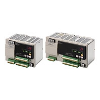
A New Type of Power Supply That Provides Safety and Maintainability
Related Contents
- Features
- Lineup
- Specifications
- Dimensions
- Catalog / Manual / CAD / Software
last update: January 14, 2025
S8AS-24006[]
| Model | S8AS-24006 | S8AS-24006N | S8AS-24006R | ||
|---|---|---|---|---|---|
| Efficiency (Typ.) | 80% min. | ||||
| Input
condi- tions |
Voltage range *1 | 100 to 240 VAC (85 to 264 VAC) | |||
| Frequency *1 | 50/60 Hz (47 to 63 Hz) | ||||
| Current | 100-V input | 3.8 A max. | |||
| 200-V input | 2.0 A max. | ||||
| Power factor *4 | 0.95 min. | ||||
| Harmonic current | EN61000-3-2 | ||||
| Leakage
current |
100-V input | 0.5 mA max. | |||
| 200-V input | 1.0 mA max. | ||||
| Inrush
current *2 |
100-V input | 25 A max. (for a cold start at 25°C) | |||
| 200-V input | 50 A max. (for a cold start at 25°C) | ||||
| Output
condi- tions |
Number of branches | 6 | |||
| Maximum cutoff output
current (per branch) |
3.8 A | ||||
| Total output current | 10 A | ||||
| Allowable voltage range *3 | ±10% (with V.ADJ) | ||||
| Ripple noise voltage | 2.0% [P-P] max. (for rated input and output voltage) *4 | ||||
| Output leakage current | 10 mA max. | ||||
| Input fluctuation | 0.5% max. (Input: 85 to 264 VAC, 100% load) *5 | ||||
| Load fluctuation
(rated input voltage) |
4.0% max. (rated input, 0% to 100% load) *5 | ||||
| Temperature fluctuation | 0.05%/°C max. | ||||
| Startup time *2 | 3,000 ms max. (for rated input and output voltage) *4 | ||||
| Output hold time *2 | 20 ms max. (for rated input and output voltage) *4 | ||||
| Func-
tions |
Tripping
functions |
Abnormal
voltage tripping |
28.8 V (Cannot be changed.) | ||
| Abnormal
current tripping *2 |
Setting range: 0.5 to 3.8
A (in 0.1-A increments) |
3.8 A (Cannot be
changed.) |
Setting range: 0.5 to 3.8
A (in 0.1-A increments) |
||
| Abnormal
total current tripping |
Branch outputs are cut off when the total output current is more than 17 A
for 2 s, 15 A for 5 s, 13 A for 10 s, or 12 A for 20 s. |
||||
| Tripping
alarm output |
Photoswitch output
30 VDC max. and 50 mA max., Leakage current: 0.1 mA max., Residual voltage: 2 V max. |
||||
| Undervoltage
detection functions |
Undervoltage
detection |
Setting range: 18.0 to
26.4 V (in 0.1-V increments) |
20.0 V (Cannot be
changed.) |
Setting range: 18.0 to
26.4 V (in 0.1-V increments) |
|
| Undervoltage
detection output |
Photoswitch output
30 VDC max. and 50 mA max., Leakage current: 0.1 mA max., Residual voltage: 2 V max. |
||||
| Maintenance
forecast monitor function |
Maintenance
forecast monitor |
Setting range: 0.0 to 5.0
yr (in 0.5-yr increments) |
0.5 yr (Cannot be
changed.) |
Setting range: 0.0 to 5.0
yr (in 0.5-yr increments) |
|
| Maintenance
forecast monitor output |
Photoswitch output
30 VDC max. and 50 mA max., Leakage current: 0.1 mA max., Residual voltage: 2 V max. |
||||
| Over-
temperature detection function |
Over-
temperature |
Setting range: 25 to
90°C (in 1°C increments) |
90°C (Cannot be
changed.) |
Setting range: 25 to
90°C |
|
| Over-
temperature output |
Photoswitch output
30 VDC max. and 50 mA max., Leakage current: 0.1 mA max., Residual voltage: 2 V max. |
||||
| Display
functions |
Output
voltage display |
Display range:17.0 to 30.0 V
Display accuracy: 2% rdg ±1 digit max. |
|||
| Output
current display |
Branch output display range: 0.0 to 4.0 A
Peak output current display range: 0.0 to 20.0 A Total current display range: 0.0 to 40.0 A Display accuracy: 5% FS (4 A) ±1 digit max. |
||||
| Maintenance
forecast monitor display |
Display range: FUL (Full)/HLF (Half)/0.0 to 5.0 yr | ||||
| Temperature
display |
Display range: -20 to 100°C
Display accuracy: 2°C ±1 digit max. |
||||
| External Tripping Input | The input can be
enabled or disabled for each branch output. 19.2 to 30.0 VDC, minimum signal width: 10 ms, tripping after input within 20 ms + the shutdown sequence set time |
All branch outputs:
Enabled (Cannot be changed.) 19.2 to 30.0 VDC, minimum signal width: 10 ms, tripping after input within 20 ms + the shutdown sequence set time |
The input can be
enabled or disabled for each branch output. 19.2 to 30.0 VDC, minimum signal width: 10 ms, tripping after input within 20 ms + the shutdown sequence set time |
||
| Startup sequence | Setting range: 0.0 to
99.9 s in 0.1-s increments |
Branch output 1: 0.0 s
(Cannot be changed.) Branch output 2: 0.4 s (Cannot be changed.) Branch output 3: 0.8 s (Cannot be changed.) Branch output 4: 1.2 s (Cannot be changed.) Branch output 5: 1.6 s (Cannot be changed.) Branch output 6: 2.0 s (Cannot be changed.) |
Setting range: 0.0 to
99.9 s in 0.1-s increments |
||
| Shutdown sequence | Setting range: 0.0 to
99.9 s in 0.1-s increments |
All branch outputs: 0.0 s
(Cannot be changed.) |
Setting range: 0.0 to
99.9 s in 0.1-s increments |
||
| Communications | Not supported | Supported (RS-485) | |||
| Sampling period | 1 ms | ||||
| Parallel connection | Not supported | ||||
| Series connection | Not supported | ||||
| Others | Ambient operating
temperature |
Refer to the derating curve (no icing or condensation). *2 | |||
| Storage temperature | -25 to 65°C | ||||
| Ambient operating humidity | 25% to 85% (storage: 25% to 90%) | ||||
| Withstand voltage | 3.0 kVAC for 1 min between all input terminals collectively and all branch
output, all I/O signal, and all communications terminals collectively (Detection current: 20 mA) 2.0 kVAC for 1 min between all inputs and protective earth (Detection current: 20 mA) 1.0 kVAC for 1 min between protective earth and all branch output, all I/O signal, and all communications terminals collectively (Detection current: 20 mA) 500 VAC for 1 min between all branch output and all I/O signal/ communications terminals collectively (Detection current: 20 mA) 500 VAC for 1 min between all I/O signal terminals collectively and communications terminals collectively (Detection current: 20 mA) 500 VAC for 1 min between all I/O signal terminals collectively and all output signal terminals collectively (detection current: 20 mA) |
||||
| Insulation resistance | 100 MΩ min. at 500 VDC between the protective earth terminal or all input
terminals collectively and all branch output, all I/O signal, and all communications terminals collectively |
||||
| Vibration resistance | No abnormality after 10 to 55 Hz at 0.375-mm single amplitude for 2 h each
in 3 directions. |
||||
| Shock resistance | No abnormality after 150 m/s2 3 times each in 6 directions. | ||||
| Output indicator | Provided (Color: green) | ||||
| Conducted EMI | Conforms to EN 61204-3 Class A and FCC Class A. | ||||
| Radiated EMI | Conforms to EN 61204-3 Class A. | ||||
| Safety standards | cULus: UL508 (Listing. Class2: Per UL1310),
CSA C22.2 No.107.1 (Class2: Per CSA C22.2 No.223) EN 62477-1 |
||||
| SEMI standard | SEMI F47-0706 (200 VAC input) | ||||
| Weight | 1,600 g max. | ||||
*1. Do not use an inverter output for the Power Supply. Inverters with an output frequency of 50/60 Hz are available, but
the rise in the internal temperature of the Power Supply may result in ignition or burning.
*2. Refer to Engineering Data on Data Sheet for details.
*3. If the output voltage adjuster (V. ADJ) is turned, the voltage will increase by more than 10% of the voltage adjustment
range. When adjusting the output voltage, confirm the actual output voltage from the Power Supply and be sure that
the load is not damaged. If the output voltage exceeds 28.8 V, all branch outputs will be cut off.
*4. Rated input and output conditions: Rated input voltage, rated frequency, rated output voltage, rated total output
current, and maximum cutoff output current.
*5. 100% load conditions: Rated output voltage, rated total output current, and maximum cutoff output current.
S8AS-48008[]
| Model | S8AS-48008 | S8AS-48008N | S8AS-48008R | ||
|---|---|---|---|---|---|
| Efficiency (Typ.) | 80% min. | ||||
| Input
condi- tions |
Voltage range *1 | 100 to 240 VAC (85 to 264 VAC) | |||
| Frequency *1 | 50/60 Hz (47 to 63 Hz) | ||||
| Current | 100-V input | 7.4 A max. | |||
| 200-V input | 3.9 A max. | ||||
| Power factor *4 | 0.95 min. | ||||
| Harmonic current | EN61000-3-2 | ||||
| Leakage
current |
100-V input | 0.5 mA max. | |||
| 200-V input | 1.0 mA max. | ||||
| Inrush
current *2 |
100-V input | 25 A max. (for a cold start at 25°C) | |||
| 200-V input | 50 A max. (for a cold start at 25°C) | ||||
| Output
condi- tions |
Number of branches | 8 | |||
| Maximum cutoff output
current (per branch) |
3.8 A | ||||
| Total output current | 20 A | ||||
| Allowable voltage range *3 | ±10% (with V.ADJ) | ||||
| Ripple noise voltage | 2.0%[P-P] max. (for rated input and output voltage) *4 | ||||
| Output leakage current | 10 mA max. | ||||
| Input fluctuation | 0.5% max. (Input: 85 to 264 VAC, 100% load) *5 | ||||
| Load fluctuation
(rated input voltage) |
4.0% max. (rated input, 0% to 100% load) *5 | ||||
| Temperature fluctuation | 0.05%/°C max. | ||||
| Startup time *2 | 3,000 ms max. (for rated input and output voltage) *4 | ||||
| Output hold time *2 | 20 ms min. (for rated input and output voltage) *4 | ||||
| Func-
tions |
Tripping
functions |
Abnormal
voltage tripping |
28.8 V (Cannot be changed.) | ||
| Abnormal
current tripping *2 |
Setting range: 0.5 to 3.8
A (in 0.1-A increments) |
3.8 A (Cannot be
changed.) |
Setting range: 0.5 to 3.8
A (in 0.1-A increments) |
||
| Abnormal
total current tripping |
Branch outputs are cut off when the total output current is more than 27 A
for 1 s, 25 A for 2 s, or 22.5 A for 5 s. |
||||
| Tripping alarm
output |
Photoswitch output
30 VDC max. and 50 mA max., Leakage current: 0.1 mA max., Residual voltage: 2 V max. |
||||
| Undervoltage
detection functions |
Undervoltage
detection |
Setting range: 18.0 to
26.4 V (in 0.1-V increments) |
20.0 V (Cannot be
changed.) |
Setting range: 18.0 to
26.4 V (in 0.1-V increments) |
|
| Undervoltage
detection output |
Photoswitch output
30 VDC max. and 50 mA max., Leakage current: 0.1 mA max., Residual voltage: 2 V max. |
||||
| Maintenance
forecast monitor function |
Maintenance
forecast monitor |
Setting range: 0.0 to 5.0
yr (in 0.5-yr increments) |
0.5 yr (Cannot be
changed.) |
Setting range: 0.0 to 5.0
yr (in 0.5-yr increments) |
|
| Maintenance
forecast monitor output |
Photoswitch output
30 VDC max. and 50 mA max., Leakage current: 0.1 mA max., Residual voltage: 2 V max. |
||||
| Over-
temperature detection function |
Over-
temperature |
Setting range: 25 to
90°C (in 1°C increments) |
90°C (Cannot be
changed.) |
Setting range: 25 to
90°C (in 1°C increments) |
|
| Over-
temperature output |
Photoswitch output
30 VDC max. and 50 mA max., Leakage current: 0.1 mA max., Residual voltage: 2 V max. |
||||
| Display
functions |
Output
voltage display |
Display range:17.0 to 30.0 V
Display accuracy: 2% rdg ±1 digit max. |
|||
| Output
current display |
Branch output display range: 0.0 to 4.0 A
Peak output current display range: 0.0 to 20.0 A Total current display range: 0.0 to 40.0 A Display accuracy: 5% FS (4 A) ±1 digit max. |
||||
| Maintenance
forecast monitor display |
Display range: FUL (Full)/HLF (Half)/0.0 to 5.0 yr | ||||
| Temperature
display |
Display range: -20 to 100°C
Display accuracy: 2°C ±1 digit max. |
||||
| External Tripping Input | The input can be
enabled or disabled for each branch output. 19.2 to 30 VDC, minimum signal width: 10 ms, tripping after input within 20 ms + the shutdown sequence set time |
All branch outputs:
Enabled (Cannot be changed.) 19.2 to 30 VDC, minimum signal width: 10 ms, tripping after input within 20 ms + the shutdown sequence set time |
The input can be
enabled or disabled for each branch output. 19.2 to 30 VDC, minimum signal width: 10 ms, tripping after input within 20 ms + the shutdown sequence set time |
||
| Startup sequence | Setting range: 0.0 to
99.9 s in 0.1-s increments |
Branch output 1: 0.0 s
(Cannot be changed.) Branch output 2: 0.4 s (Cannot be changed.) Branch output 3: 0.8 s (Cannot be changed.) Branch output 4: 1.2 s (Cannot be changed.) Branch output 5: 1.6 s (Cannot be changed.) Branch output 6: 2.0 s (Cannot be changed.) Branch output 7: 2.4 s (Cannot be changed.) Branch output 8: 2.8 s (Cannot be changed.) |
Setting range: 0.0 to
99.9 s in 0.1-s increments |
||
| Shutdown sequence | Setting range: 0.0 to
99.9 s in 0.1-s increments |
All branch outputs: 0.0 s
(Cannot be changed.) |
Setting range: 0.0 to
99.9 s in 0.1-s increments |
||
| Communications | Not supported | Supported (RS-485) | |||
| Sampling period | 1 ms | ||||
| Parallel connection | Not supported | ||||
| Series connection | Not supported | ||||
| Others | Ambient operating
temperature |
Refer to the derating curve (no icing or condensation). *2 | |||
| Storage temperature | -25 to 65°C | ||||
| Ambient operating humidity | 25% to 85% (storage: 25% to 90%) | ||||
| Withstand voltage | 3.0 kVAC for 1 min between all input terminals collectively and all branch
output, all I/O signal, and all communications terminals collectively (Detection current: 20 mA) 2.0 kVAC for 1 min between all inputs and protective earth (Detection current: 20 mA) 1.0 kVAC for 1 min between protective earth and all branch output, all I/O signal, and all communications terminals collectively (Detection current: 30 mA) 500 VAC for 1 min between all branch output and all I/O signal/ communications terminals collectively (Detection current: 20 mA) 500 VAC for 1 min between all I/O signal terminals collectively and communications terminals collectively (Detection current: 20 mA) 500 VAC for 1 min between all I/O signal terminals collectively and all output signal terminals collectively (detection current: 20 mA) |
||||
| Insulation resistance | 100 MΩ min. at 500 VDC between the protective earth terminal or all input
terminals collectively and all branch output, all I/O signal, and all communications terminals collectively |
||||
| Vibration resistance | No abnormality after 10 to 55 Hz at 0.375-mm single amplitude for 2 h each
in 3 directions. |
||||
| Shock resistance | No abnormality after 150 m/s2 3 times each in 6 directions. | ||||
| Output indicator | Provided (Color: green) | ||||
| Conducted EMI | Conforms to EN 61204-3 Class A and FCC Class A. | ||||
| Radiated EMI | Conforms to EN 61204-3 Class A. | ||||
| Safety standards (pending) | cULus: UL508 (Listing. Class2: Per UL1310),
CSA C22.2 No.107.1 (Class2: Per CSA C22.2 No.223) EN 62477-1 |
||||
| SEMI standard | SEMI F47-0706 (200 VAC input) | ||||
| Weight | 2,400 g max. | ||||
*1. Do not use an inverter output for the Power Supply. Inverters with an output frequency of 50/60 Hz are available, but
the rise in the internal temperature of the Power Supply may result in ignition or burning.
*2. Refer to Engineering Data on Data Sheet for details.
*3. If the output voltage adjuster (V. ADJ) is turned, the voltage will increase by more than 10% of the voltage adjustment
range. When adjusting the output voltage, confirm the actual output voltage from the Power Supply and be sure that
the load is not damaged. If the output voltage exceeds 28.8 V, all branch outputs will be cut off.
*4. Rated input and output conditions: Rated input voltage, rated frequency, rated output voltage, rated total output
current, and maximum cutoff output current.
*5. 100% load conditions: Rated output voltage, rated total output current, and maximum cutoff output current.
the rise in the internal temperature of the Power Supply may result in ignition or burning.
*2. Refer to Engineering Data on Data Sheet for details.
*3. If the output voltage adjuster (V. ADJ) is turned, the voltage will increase by more than 10% of the voltage adjustment
range. When adjusting the output voltage, confirm the actual output voltage from the Power Supply and be sure that
the load is not damaged. If the output voltage exceeds 28.8 V, all branch outputs will be cut off.
*4. Rated input and output conditions: Rated input voltage, rated frequency, rated output voltage, rated total output
current, and maximum cutoff output current.
*5. 100% load conditions: Rated output voltage, rated total output current, and maximum cutoff output current.
last update: January 14, 2025