Discontinued On Mar. 2021
E5AR-T
Programmable Digital Controller
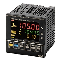
A new High-speed, High-precision Digital Controller that is Programmable!
* Information in this page is a reference that you created on the basis of information in the product catalog before the end of production, may be different from the current situation, such as goods for / supported standards options / price / features of the product. Before using, please check the compatibility and safety system.
Related Contents
- Features
- Lineup
- Specifications
- Dimensions
- Catalog / Manual / CAD / Software
last update: August 5, 2015
Ratings
|
Supply voltage *2 |
CE marking | 100 to 240 VAC, 50/60 Hz | 24 VAC, 50/60 Hz; 24 VDC |
|---|---|---|---|
| UL certification | 100 to 120 VAC, 50/60 Hz | ||
| Operating voltage range | 85% to 110% of rated supply voltage | ||
| Power consumption | 22 VA max. (with maximum load) | 15 VA/10 W max. (with maximum load) | |
| Sensor input *3 | Thermocouple: K, J, T, E, L, U, N, R, S, B, W Platinum resistance thermometer: Pt100 Current input: 4 to 20 mA DC, 0 to 20 mA DC (including remote SP input) Voltage input: 1 to 5 VDC, 0 to 5 VDC, 0 to 10 VDC (including remote SP input) (Input impedance: 150 Ω for current input, approx. 1 MΩ for voltage input) |
||
|
Control output |
Voltage (pulse) output |
12 VDC, 40 mA max. with short-circuit protection circuit (E5AR-TQQE3MW-FLK: 21 mA max.) | |
| Current output | 0 to 20 mA DC, 4 to 20 mA DC; load: 500 Ω max. (including transfer output) (Resolution: Approx. 54,000 for 0 to 20 mA DC; Approx. 43,000 for 4 to 20 mA DC) |
||
| Relay output | Position-proportional control type (open, closed) N.O., 250 VAC, 1 A (including inrush current) |
||
| Auxiliary output | Relay Output N.O., 250 VAC, 1 A (resistive load) Transistor Output Maximum load voltage: 30 VDC; Maximum load current: 50 mA; Residual voltage: 1.5 V max.; Leakage current: 0.4 mA max. |
||
| Potentiometer input | 100 Ω to 2.5 kΩ | ||
| Event input | Contact | Input ON: 1 kΩ max.; OFF: 100 kΩ min. | |
| No-contact | Input ON: Residual voltage of 1.5 V max.; OFF: Leakage current of 0.1 mA max. | ||
| Event input | Short-circuit: Approx. 4 mA | ||
| Remote SP input | Refer to the information on sensor input. | ||
| Transfer output | Refer to the information on control output. | ||
| Control method | 2-PID or ON/OFF control | ||
| Setting method | Digital setting using front panel keys or setting using serial communications | ||
| Indication method | 7-segment digital display and single-lighting indicator Character Height PV display: 12.8 mm; SV display: 7.7 mm; MV display: 7.7 mm |
||
| Other functions | Depends on model. | ||
| Ambient operating temperature | -10 to 55°C (with no icing or condensation) For 3 years of assured use: -10 to 50°C (with no icing or condensation) |
||
| Ambient operating humidity | 25% to 85% | ||
| Storage temperature | -25 to 65°C (with no icing or condensation) | ||
*1. Do not use an inverter output as the power supply. (Refer to Safety Precautions for All E5[]R Models.)
*2. The supply voltage (i.e., 100 to 240 VAC or 24 VAC/VDC) depends on the model. Be sure to specify the required
type when ordering.
*3. The Controller is equipped with multiple sensor input. Temperature input or analog input can be selected with the
input type setting switch. There is basic insulation between power supply and input terminals, power supply and
output terminals, and input and output terminals.
Input Ranges
Platinum Resistance Thermometer, Thermocouple, Current, or Voltage Input
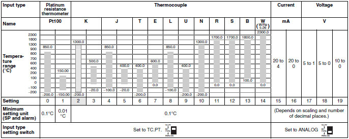
Note: The shaded area indicates the setting status at the time of purchase.
Characteristics
| Indication accuracy | Thermocouple input with cold junction compensation: (±0.1% of PV or ±1°C, whichever is
greater) ±1 digit max. (See note 1.) Thermocouple input without cold junction compensation: (±0.1% FS or ±1°C, whichever is smaller) ±1 digit (See note 2.) Analog input: ±0.1% FS ±1 digit max. Platinum resistance thermometer input: (±0.1% of PV or ±0.5°C, whichever is greater) ±1 digit max. Position-proportional potentiometer input: ±5% FS ±1 digit max. |
|---|---|
| Control mode | Standard control (heating or cooling control), heating/cooling control, standard control with
remote SP (2-input models only), heating/cool-ing control with remote SP (2-input models only), cascade standard control (2-input models only), cascade heating/cooling control (2- input models only), proportional control (2-input models only), position-proportional control (control-valve control models only) |
| Influence of
temperature |
Thermocouple input (R, S, B, W): (±1% of PV or ±10°C, whichever is greater) ±1 digit max.
Other thermocouple input: (±1% of PV or ±4°C, whichever is greater) ±1 digit max. *K thermocouple at -100°C max.: ±10°C max. Platinum resistance thermometer: (±1% of PV or ±2°C, whichever is greater) ±1 digit max. Analog input: (±1%FS) ±1 digit max. |
| Influence of voltage | |
| Influence of EMS.
(at EN61326-1) |
|
| Control period | 0.2 to 99.0 s (in units of 0.1 s) for time-proportioning control output |
| Proportional band (P) | 0.00% to 999.99% FS (in units of 0.01% FS) |
| Integral time (I) | 0.0 to 3,999.9 s (in units of 0.1 s) |
| Derivative time (D) | 0.0 to 3,999.9 s (in units of 0.1 s) |
| Hysteresis | 0.01% to 99.99% FS (in units of 0.01% FS) |
| Manual reset value | 0.0% to 100.0% (in units of 0.1% FS) |
| Alarm setting range | -19,999 to 99,999 EU (See note 3.)
(The decimal point position depends on the input type and the decimal point position setting.) |
| Input sampling period | 50 ms |
| Insulation resistance | 20 MΩ min. (at 500 VDC) |
| Dielectric strength | 2,000 VAC, 50/60 Hz for 1 min (between charged terminals of different polarities) |
| Vibration resistance
(malfunction) |
10 to 55 Hz, 20 m/s2 for 10 min each in X, Y, and Z directions |
| Shock resistance
(malfunction) |
100 m/s2, 3 times each in X, Y, and Z directions |
| Inrush current | 100 to 240-VAC models: 50 A max.
24 VAC/VDC models: 30 A max. |
| Weight | Controller only: Approx. 450 g; Mounting bracket: Approx. 60 g; Terminal cover: Approx. 30 g |
| Degree of protection | Front panel: NEMA4X for indoor use; Rear case: IP20; Terminals: IP00 |
| Memory protection | Non-volatile memory (number of writes: 100,000) |
| Applicable standards | UL 61010C-1, CSA C22.2 No. 1010-1
(Power supply voltage: 100 to 120 VAC): Pollution degree 2/Overvoltage category 2 EN 61010-1 (IEC 61010-1) (Power supply voltage: 100 to 240 VAC): Pollution degree 2/ Overvoltage category 2 |
| EMC | EMI: EN61326-1 (See note 4.)
Radiated Interference Electromagnetic Field Strength: EN55011 Group 1 Class A Noise Terminal Voltage: EN55011 Group 1 Class A EMS: EN61326-1 (See note 4.) ESD Immunity: EN61000-4-2: 4 kV contact discharge (level 2), 8 kV air discharge (level 3) Electromagnetic Immunity: EN61000-4-3: 10 V/m (amplitude-modulated, 80 MHz to 1 GHz, 1.4 GHz to 2 GHz) (level 3) Burst Noise Immunity: EN61000-4-4:2 kV power line (level 3), 2 kV output line (relay output) (level 4), 1 kV measurement line, I/O signal line (level 4), 1 kV communications line (level 3) Conducted Disturbance Immunity: EN61000-4-6: 3 V (0.15 to 80 MHz) (level 3) Surge Immunity: EN61000-4-5:1 kV line to line (power line, output line (relay output)) (level 2), 2 kV line to ground (power line, output line (relay output)) (level 3) Power Frequency Magnetic Field Immunity: EN61000-4-8: 30 A/m (50 Hz) continuous field Voltage Dip/Interrupting Immunity: EN61000-4-11: 0.5 cycle, 100% (rated voltage) |
Note 1: K-, T-, or N-type thermocouple at −100°C max.: ±2°C ±1 digit max.
U- or L-type thermocouple: ±2°C ±1 digit max.
B-type thermocouple at 400°C max.: No accuracy specification.
R- or S-type thermocouple at 200°C max.: ±3°C ±1 digit max.
W-type thermocouple: (±0.3% of PV or ±3°C, whichever is greater) ±1 digit max.
2: U- or L-type thermocouple: ±1°C ±1 digit
R- or S-type thermocouple at 200°C max.: ±1.5°C ±1 digit
3: “EU” (Engineering Unit) represents the unit after scaling. If a temperature sensor is used, it is either °C or °F.
4: Industrial electromagnetic environment (EN/IEC 61326-1 Table 2)
Communications Specifications
| Transmission path connection | Multiple points |
|---|---|
| Communications method | RS-485 (two-wire, half duplex) |
| Synchronization method | Start-stop synchronization |
| Baud rate | 9,600, 19,200, or 38,400 bps |
| Transmission code | ASCII |
| Data bit length | 7 or 8 bits |
| Stop bit length | 1 or 2 bits |
| Error detection | Vertical parity (none, even, odd)
Block check character (BCC): CompoWay/F CRC-16: Modbus |
| Flow control | None |
| Interface | RS-485 |
| Retry function | None |
| Communications buffer | 217 bytes |
| Communications response send wait time | 0 to 99 ms, Default: 20 ms |
Program Control Functions
| Number of programs (patterns) | 32 (with 8 segments/program) | |
|---|---|---|
| Number of segments (steps) | 32 (with 8 programs) | |
| Maximum number of segments | 256 | |
| Segment setting method | Time setting (Segment set with set point and time.) Gradient setting (Segment set with set point, gradient, and time.) |
|
| Segment times | 0 h 0 min to 99 h 59 min 0 min 0 s to 99 min 59 s 0 min 00.0 s to 99 min 59.9 s |
|
|
Alarm group number specifications |
Number of groups | 4 |
| Setting method | Set separately for each program. | |
| Reset operation | Select either stopping control or fixed SP operation. | |
| Startup operation | Select continuing, resetting, manual operation, run mode, or ramp back operation. | |
| PID sets | Number of sets | 8 |
| Setting method | Set separately for each program (automatic PID group selection also supported). | |
| Alarm SP function | Select from ramp SP and target SP. | |
|
Program status control |
Segment operation | Advance, hold, and back |
| Program operation | Program repetitions and program links | |
| Wait operation | Wait method | Select from waiting at segment ends and always waiting. |
| Wait width setting | Wait width upper limit and lower limit set separately for each program. | |
| Setting method | ON/OFF setting for each segment | |
| Time signals | Number of outputs | 6 |
|
Number of ON/OFF operations |
3 each per output | |
| Setting method | Set separately for each program. | |
| Segment outputs | Number of outputs | 10 |
| Setting method | ON/OFF set for each segment. | |
| Program status output | Program end output (pulse width can be set) Segment number output |
|
|
Program startup operation |
PV start | Select from segment 1 set point, slope-priority PV start, and time-priority PV start. |
| Standby | Standby | |
| Operation end operation | Select from resetting, continuing control at final set point, and fixed SP control. | |
| Number of event inputs | 10 max. | |
last update: August 5, 2015
 Product Category
- Control Components
-
Temperature Controllers
-
Discontinued
- E5AR-T
-
Discontinued
-