Discontinued On Mar. 2021
E5ER
Digital Controllers
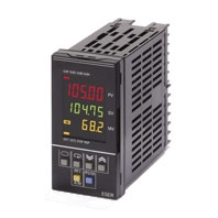
E5ER Digital Controllers offer high speed,high precision, and multiple I/O and use a 5-digit, 3-row LCD display for high visual clarity.
* Information in this page is a reference that you created on the basis of information in the product catalog before the end of production, may be different from the current situation, such as goods for / supported standards options / price / features of the product. Before using, please check the compatibility and safety system.
Related Contents
- Features
- Lineup
- Specifications
- Dimensions
- Catalog / Manual / CAD / Software
last update: September 1, 2017
Ratings
| Supply voltage
(See note 1.) |
100 to 240 VAC, 50/60 Hz | 24 VAC, 50/60 Hz; 24 VDC | |
|---|---|---|---|
| Operating voltage range | 85% to 110% of rated supply voltage | ||
| Power consumption | 17 VA max. (with maximum load) | 11 VA/7 W max. (with maximum load) | |
| Sensor input (See note 2.) | Thermocouple: K, J, T, E, L, U, N, R, S, B, W
Platinum resistance thermometer: Pt100 Current input: 4 to 20 mA DC, 0 to 20 mA DC (including remote SP input) Voltage input: 1 to 5 VDC, 0 to 5 VDC, 0 to 10 VDC (including remote SP input) (Input impedance: 150 Ω for current input, approx. 1 MΩ for voltage input) |
||
| Control
output |
Voltage (pulse)
output |
12 VDC, 40 mA max. with short-circuit protection circuit | |
| Current output | 0 to 20 mA DC, 4 to 20 mA DC; load: 500 Ω max. (including transfer output)
(Resolution: Approx. 54,000 for 0 to 20 mA DC; Approx. 43,000 for 4 to 20 mA DC) |
||
| Relay output | Position-proportional control type (open, closed)
N.O., 250 VAC, 1 A (including inrush current) |
||
| Auxiliary output | Relay Output
N.O., 250 VAC, 1 A (resistive load) Transistor Output Maximum load voltage: 30 VDC; Maximum load current: 50 mA; Residual voltage: 1.5 V max.; Leakage current: 0.4 mA max. |
||
| Potentiometer input | 100 Ω to 2.5 kΩ | ||
| Event
input |
Contact | Input ON: 1 kΩ max.; OFF: 100 kΩ min. | |
| No-contact | Input ON: Residual voltage of 1.5 V max.; OFF: Leakage current of 0.1 mA max. | ||
| Short circuit current: Approx. 4 mA | |||
| Remote SP input | Refer to the information on sensor input. | ||
| Transfer output | Refer to the information on control output. | ||
| Control method | 2-PID or ON/OFF control | ||
| Setting method | Digital setting using front panel keys or setting using serial communications | ||
| Indication method | 7-segment digital display and single-lighting indicator
Character Height PV: 9.5 mm; SV: 7.2 mm; MV: 7.2 mm |
||
| Other functions | Depends on model. | ||
| Ambient operating
temperature |
-10 to 55°C (with no icing or condensation)
For 3 years of assured use: -10 to 50°C (with no icing or condensation) |
||
| Ambient operating
humidity |
25% to 85% | ||
| Storage temperature | -25 to 65°C (with no icing or condensation) | ||
Note 1: The supply voltage (i.e., 100 to 240 VAC or 24 VAC/VDC) depends on the model. Be sure to specify the required
type when ordering.
2: The Controller is equipped with multiple sensor input. Temperature input or analog input can be selected with the
input type setting switch. There is basic insulation between power supply and input terminals, power supply and
output terminals, and input and output terminals.
3: Do not use an inverter output as the power supply. (Refer to Safety Precautions for All E5[]R Models.)
Input Ranges
Platinum Resistance Thermometer, Thermocouple, Current, or Voltage Input
Characteristics
| Indication accuracy | Thermocouple input with cold junction compensation: (±0.1% of PV or ±1°C, whichever is greater) ±1 digit max. (See note 1.)
Thermocouple input without cold junction compensation: (±0.1% FS or ±1°C, whichever is smaller) ±1 digit (See note 2.) Analog input: ±0.1% FS ±1 digit max. Platinum resistance thermometer input: (±0.1% of PV or ±0.5°C, whichever is greater) ±1 digit max. Position-proportional potentiometer input: ±5% FS ±1 digit max. |
|---|---|
| Control mode | Standard control (heating or cooling control), heating/cooling control, standard control with remote SP (2-input models only), heating/cooling
control with remote SP (2-input models only), cascade standard control (2-input models only), cascade heating/cooling control (2-input models only), proportional control (2-input models only), position-proportional control (control-valve control models only) |
| Influence of temperature | Thermocouple input (R, S, B, W): (±1% of PV or ±10°C, whichever is greater) ±1 digit max.
Other thermocouple input: (±1% of PV or ±4°C, whichever is greater) ±1 digit max. ∗K-type thermocouple at -100°C max.: ±10°C max. Platinum resistance thermometer: (±1% of PV or ±2°C, whichever is greater) ±1 digit max. Analog input: (±1%FS) ±1 digit max. |
| Influence of temperature | |
| Influence of EMS.
(at EN61326-1) |
|
| Control period | 0.2 to 99.0 s (in units of 0.1 s) for time-proportioning control output |
| Proportional band (P) | 0.00% to 999.99% FS (in units of 0.01% FS) |
| Integral time (I) | 0.0 to 3,999.9 s (in units of 0.1 s) |
| Derivative time (D) | 0.0 to 3,999.9 s (in units of 0.1 s) |
| Hysteresis | 0.01% to 99.99% FS (in units of 0.01% FS) |
| Manual reset value | 0.0% to 100.0% (in units of 0.1% FS) |
| Alarm setting range | -19,999 to 99,999 EU (See note 3.) (The decimal point position depends on the input type and the decimal point position setting.) |
| Input sampling period | 50 ms |
| Insulation resistance | 20 MΩ min. (at 500 VDC) |
| Dielectric strength | 2,000 VAC, 50/60 Hz for 1 min (between charged terminals of different polarities) |
| Vibration resistance | 10 to 55 Hz, 20 m/s2 for 10 min each in X, Y, and Z directions |
| Shock resistance | 100 m/s2, 3 times each in X, Y, and Z directions |
| Inrush current | 100 to 240-VAC models: 50 A max.
24 VAC/VDC models: 30 A max. |
| Weight | Controller only: Approx. 330 g; Mounting bracket: Approx. 60 g; Terminal cover: Approx. 16 g |
| Degree of protection | Front panel: NEMA4X for indoor use (equivalent to IP66); Rear case: IP20; Terminals: IP00 |
| Memory protection | Non-volatile memory (number of writes: 100,000) |
| Applicable standards | UL61010C-1, CSA C22.2 No. 1010-1
EN61010-1 (IEC61010-1): Pollution degree 2/overvoltage category 2 |
| EMC | EMI: EN61326-1 (See note 5.)
Radiated Interference Electromagnetic Field Strength: EN55011 Group 1 Class A Noise Terminal Voltage: EN55011 Group 1 Class A EMS: EN61326-1 (See note 5.) ESD Immunity: EN61000-4-2: 4 kV contact discharge (level 2) 8 kV air discharge (level 3) Electromagnetic Immunity: EN61000-4-3: 10 V/m (amplitude-modulated, 80 MHz to 1 GHz, 1.4 GHz to 2 GHz) (level 3) Burst Noise Immunity: EN61000-4-4: 2 kV power line (level 3) 2 kV output line (relay output) (level 4) 1 kV measurement line, I/O signal line (level 4) 1 kV communications line (level 3) Conducted Disturbance Immunity: EN61000-4-6: 3 V (0.15 to 80 MHz) (level 3) Surge Immunity: EN61000-4-5: 1 kV line to line (power line, output line (relay output)) (level 2) 2 kV line to ground (power line, output line (relay output)) (level 3) Power Frequency Magnetic Field Immunity: EN61000-4-8: 30 A/m (50 Hz) continuous field Voltage Dip/Interrupting Immunity: EN61000-4-11: 0.5 cycle, 100% (rated voltage) |
Note: 1. K-, T-, or N-type thermocouple at -100°C max.: ±2°C ±1 digit max.
U- or L-type thermocouple: ±2°C ±1 digit max.
B-type thermocouple at 400°C max.: No accuracy specification.
R- or S-type thermocouple at 200°C max.: ±3°C ±1 digit max.
W-type thermocouple: (±0.3% of PV or ±3°C, whichever is greater) ±1 digit max.
2. U- or L-type thermocouple: ±1°C ±1 digit
R- or S-type thermocouple at 200°C max.: ±1.5°C ±1 digit
3. "EU" (Engineering Unit) represents the unit after scaling. If a temperature sensor is used it is either °C or °F.
4. Conditions: Ambient temperature from -10 to 23 to 55°C and voltage of -15% to 10% of rated voltage.
5. Industrial electromagnetic environment (EN/IEC 61326-1 Table 2)
Communications Specifications
| Transmission path connection | Multiple points |
|---|---|
| Communications method | RS-485 (two-wire, half duplex) |
| Synchronization method | Start-stop synchronization |
| Baud rate | 9,600, 19,200, or 384,000 bps |
| Transmission code | ASCII |
| Data bit length | 7 or 8 bits |
| Stop bit length | 1 or 2 bits |
| Error detection | Vertical parity (none, even, odd) Block check character (BCC): CompoWay/F CRC-16: Modbus |
| Flow control | None |
| Interface | RS-485 |
| Retry function | None |
| Communications buffer | 217 bytes |
| Communications response send wait time | 0 to 99 ms, Default: 20 ms |
DeviceNet
| Item | Specifications | ||||
|---|---|---|---|---|---|
| Communications protocol | Conforms to DeviceNet | ||||
| Communications
functions |
Remote I/O
communications |
• Master-slave connections (polling, bit-strobe, COS, or cyclic)
• Conform to DeviceNet specifications. |
|||
| I/O allocations | • Can allocate any I/O data from the Configurator.
• Can allocate any data, such as parameters specific to the Devicenet, and the Digital Controller variable area. • Up to 2 blocks for the IN Area, up to a total of 100 words. • One block for the OUT Area, up to 100 words (first word is always allocated to Output Enable Bits). |
||||
| Message
communications |
• Explicit message communications
• CompoWay/F communications commands can be sent (commands are sent in explicit message format). |
||||
| Connection format | Combination of multidrop and T-branch connections (for trunk and drop lines) | ||||
| Baud rate | DeviceNet: 500, 250, or 125 kbps, or automatic detection of master baud rate | ||||
| Communications media | Special 5-wire cable (2 signal lines, 2 power lines, and 1 shield line) | ||||
| Communications distance | Baud rate | Network length | Drop line length | Total drop line length | |
| 500 kbps | 100 m max. (100 m max.) | 6 m max. | 39 m max. | ||
| 250 kbps | 250 m max. (100 m max.) | 6 m max. | 78 m max. | ||
| 125 kbps | 500 m max. (100 m max.) | 6 m max. | 156 m max. | ||
| The values in parentheses apply when Thin Cables are used. | |||||
| Supply voltage | DeviceNet power supply: 24 VDC | ||||
| Allowable voltage range | DeviceNet power supply: 11 to 25 VDC | ||||
| Current consumption | 50 mA max. (24 VDC) | ||||
| Maximum number of nodes that can
be connected |
64 (includes Configurator when used) | ||||
| Maximum number of slaves that can
be connected |
63 | ||||
| Error control | CRC error detection | ||||
| Power supply | Power supplied from DeviceNet communications connector. | ||||
last update: September 1, 2017
 Product Category
- Control Components
-
Temperature Controllers
-
Discontinued
- E5ER
-
Discontinued
-