R88M-G, R7D-BP
AC Servomotors and SMARTSTEP 2-series Servo Drives with Pulse String Inputs
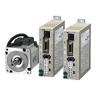
Advanced Functionality in a Super Compact Design.
Related Contents
- Features
- Lineup
- Specifications
- Dimensions
- Catalog / Manual / CAD / Software
last update: January 23, 2023
Servo Drive Specifications (R7D-BP)
General Specifications
| Item | Specifications | ||
|---|---|---|---|
| Ambient operating temperature
Ambient operating humidity |
0 to 55 °C, 90% max. (with no condensation) | ||
| Ambient storage temperature
Ambient storage humidity |
-20 to 65 °C, 90% max. (with no condensation) | ||
| Storage and operating atmosphere | No corrosive gasses, no dust, no iron dust, no exposure to moisture or
cutting oil |
||
| Vibration resistance | 10 to 60 Hz; acceleration: 5.9 m/s2 (0.6 G) max. | ||
| Impact resistance | Acceleration of 19.6 m/s2 max. 3 times each in X, Y, and Z directions. | ||
| Insulation resistance | Between power supply/power line terminals and frame ground: 0.5 MΩ.
min. (at 500 VDC) |
||
| Dielectric strength | Between power supply/power line terminals and frame ground: 1,500 VAC for 1 min at 50/60 Hz | ||
| Altitude | 1,000 m above sea level max. (860 hp min.) | ||
| Degree of protection | Built into panel (IP10). | ||
| International
standards |
EU Directives
and UK legislation |
EMC | EN 55011 class A group 1
EN 61000-6-2 |
| Low Voltage | EN61800-5-1 | ||
| UL standards | UL 508C | ||
| cUL standards | cUL C22.2 No.14 | ||
| Korean Radio Regulations
(KC) |
Certified | ||
Note: 1. The above items reflect individual evaluation testing. The results may differ under compound conditions.
Note: 2. Always disconnect all connections to the Servo Drive before you perform insulation resistance tests on it. If you
perform an insulation resistance test while the Servo Drive is connected, the Servo Drive may be damaged.
Never perform dielectric strength tests on the Servo Drive. Failure to follow this precaution may result in
damaging internal elements.
Note: 3. Depending on the operating conditions, some Servo Drive parts will require maintenance.
Note: 4. The service life of the Servo Drive is 50,000 hours at an average ambient temperature of 40°C at 80% of the
rated torque (excluding axial-flow fan).
Characteristics
100 VAC specification
| Item | Servo Drive model | ||
|---|---|---|---|
| R7D-BPA5L | R7D-BP01L | R7D-BP02L | |
| Continuous output current (rms) | 1.0 A | 1.6 A | 2.5 A |
| Momentary maximum output current (rms) | 3.3 A | 5.1 A | 7.5 A |
| Power supply capacity | 0.16 KVA | 0.25 KVA | 0.42 KVA |
| Input power supply voltage (main circuit) | Single-phase 100 to 115 VAC (85 to 127 V), 50/60 Hz | ||
| Input power supply current (rms) (main circuit) | 1.4 A | 2.2 A | 3.7 A |
| Heat generated (main circuit) | 12 W | 16 W | 22 W |
| Control method | All-digital servo | ||
| Inverter method | IGBT-driven PWM method | ||
| PWM frequency | 12 kHz | 6 kHz | |
| Maximum response frequency (command pulses) | Line drive: 500 kpps, Open collector: 200 kpps | ||
| Weight | 0.35 kg | 0.42 kg | |
| Applicable motor capacity | 50 W | 100 W | 200 W |
200 VAC specification
| Item | Servo Drive model | |||
|---|---|---|---|---|
| R7D-BP01H | R7D-BP02HH | R7D-BP02H | R7D-BP04H | |
| Continuous output current (rms) | 1.0 A | 1.6 A | 1.6 A | 2.5 A |
| Momentary maximum output current (rms) | 3.3 A | 4.9 A | 4.9 A | 7.8 A |
| Power supply capacity | 0.27 KVA
(0.30 KVA) * |
0.35 KVA | 0.42 KVA | 0.69 KVA
(0.77 KVA) * |
| Input power supply voltage (main circuit) | Both single-phase and three-phase
200 to 240 VAC (170 to 264 V), 50/60 Hz |
|||
| Input power supply current (rms) (main
circuit) |
0.7 A
(1.5 A) * |
1.6 A | 1.1 A | 1.8 A
(3.5 A) * |
| Heat generated (main circuit) | 14 W | 16 W | 20 W | 26W |
| Control method | All-digital servo | |||
| Inverter method | IGBT-driven PWM method | |||
| PWM frequency | 12 kHz | 6 kHz | ||
| Maximum response frequency (command
pulses) |
Line drive: 500 kpps, Open collector: 200 kpps | |||
| Weight | 0.35 kg | 0.42 kg | 0.35 kg | 0.42 kg |
| Applicable motor capacity | 100 W | 200 W | 200 W | 400 W |
* Values inside parentheses ( ) are for single-phase 200-V use.
Servomotor Specifications (R88M-G)
General Specifications
| Item | Specifications | ||
|---|---|---|---|
| Ambient operating temperature
Ambient operating humidity |
0 to 40 °C, 85% max. (with no condensation) | ||
| Ambient storage temperature
Ambient storage humidity |
- 20 to 65 °C, 85% max. (with no condensation) | ||
| Storage and operating atmosphere | No corrosive gases | ||
| Vibration resistance | 49 m/s2 max. in the X, Y, and Z directions | ||
| Impact resistance | Acceleration of 98 m/s2 max. 3 times each in the X, Y, and Z directions | ||
| Insulation resistance | 20 MΩ min. at 500 VDC between the power terminals and FG terminal | ||
| Dielectric strength | 1,500 VAC (50 or 60 Hz) for 1 minute between the power terminals and
FG terminal |
||
| Operating position | Any direction | ||
| Insulation class | Type B | ||
| Construction | Totally-enclosed, self-cooling | ||
| Degree of protection | IP65 (excluding the through-shaft portion) | ||
| Vibration class | V-15 | ||
| Mounting method | Flange-mounting | ||
| International
standards |
EU Directives
and UK legislation |
Low Voltage | IEC 60034-5:2001 |
| UL standards | UL 1004 File No. E179189 | ||
| cUL standards | cUL 22.2, No.100 | ||
Note: Always disconnect all connections to the Servo Drive before you perform insulation resistance tests on it. If you
perform an insulation resistance test while the Servo Drive is connected, the Servo Drive may be damaged.
Never perform dielectric strength tests on the Servo Drive. Failure to follow this precaution may result in damaging
internal elements.
perform an insulation resistance test while the Servo Drive is connected, the Servo Drive may be damaged.
Never perform dielectric strength tests on the Servo Drive. Failure to follow this precaution may result in damaging
internal elements.
Characteristics
3,000-r/min Cylindrical Servomotors
100 VAC specification
| Item | Unit | R88M-G05030H | R88M-G10030L | R88M-G20030L | |
|---|---|---|---|---|---|
| Rated output *1 | W | 50 | 100 | 200 | |
| Rated torque *1 | Nm | 0.16 | 0.32 | 0.64 | |
| Rated rotation speed | r/min | 3000 | |||
| Max. rotation speed | r/min | 5000 | |||
| Max. momentary torque *1 | Nm | 0.48 | 0.95 | 1.78 | |
| Rated current *1 | A (rms) | 1.1 | 1.7 | 2.5 | |
| Max. momentary current *1 | A (rms) | 3.4 | 5.1 | 7.6 | |
| Rotor inertia | kg·m2 | 2.5 × 10⁻⁶ | 5.1 × 10⁻⁶ | 1.4 × 10⁻⁵ | |
| Applicable load inertia | --- | 30 times rotor inertia max. | |||
| Power rate *1 | kW/s | 10.4 | 20.1 | 30.3 | |
| Allowable radial load *2 | N | 68 | 68 | 245 | |
| Allowable thrust load *2 | N | 58 | 58 | 98 | |
| Weight | Without brake | kg | 0.3 | 0.5 | 0.8 |
| With brake | kg | 0.5 | 0.7 | 1.3 | |
| Radiation shield dimensions (material) | --- | 100 × 80 × t10 (Al) | 130 × 120 × t12 (Al) | ||
| Brake
specifications |
Brake inertia | kg·m2 | 2.0 × 10⁻⁷ | 2.0 × 10⁻⁷ | 1.8 × 10⁻⁶ |
| Excitation voltage *3 | V | 24 VDC ± 10% | |||
| Power consumption
(at 20 °C) |
W | 7 | 7 | 9 | |
| Current consumption
(at 20 °C) |
A | 0.3 | 0.3 | 0.36 | |
| Static friction torque | Nm | 0.29 min. | 0.29 min. | 1.27 min. | |
| Attraction time *4 | ms | 35 max. | 35 max. | 50 max. | |
| Release time *4 | ms | 20 max. | 20 max. | 15 max. | |
| Backlash | ± 1 ° | ||||
| Allowable work per
braking operation |
J | 39.2 | 39.2 | 137 | |
| Allowable total work | J | 4.9 × 10³ | 4.9 × 10³ | 44.1 × 10³ | |
| Allowable angular
acceleration |
rad/s2 | 30,000 max.
(Speed of 2,800 r/min minimum must not be stopped in less than 10 ms) |
|||
| Brake life | --- | 10,000,000 operations min. | |||
| Rating | --- | Continuous | |||
| Insulation class | --- | Type F | |||
*1. These are the values when the Servomotor is combined with a Servo Drive at room temperature.
The momentary maximum torque shown above indicates the standard value.
*2. The allowable radial and thrust loads are the values determined for a service life of 20,000 hours at normal
operating temperatures. The values are also for the locations shown in the following diagram.
*3. The brakes operate when the circuit is open (i.e., they are released when voltage is applied).
*4. The operation time is the measured value (reference value) with a varistor installed as a surge suppressor.
200 VAC specification
| Item | Unit | R88M-
G05030H |
R88M-
G10030H |
R88M-
G20030H |
R88M-
G40030H |
|
|---|---|---|---|---|---|---|
| Rated output *1 | W | 50 | 100 | 200 | 400 | |
| Rated torque *1 | Nm | 0.16 | 0.32 | 0.64 | 1.3 | |
| Rated rotation speed | r/min | 3000 | ||||
| Max. rotation speed | r/min | 5000 | ||||
| Max. momentary torque *1 | N·Em | 0.48 | 0.95 | 1.78 | 3.60 | |
| Rated current *1 | A (rms) | 1.1 | 1.1 | 1.6 | 2.6 | |
| Max. momentary current *1 | A (rms) | 3.4 | 3.4 | 4.9 | 7.9 | |
| Rotor inertia | kg·m 2 | 2.5 × 10⁻⁶ | 5.1 × 10⁻⁶ | 1.4 × 10⁻⁵ | 2.6 × 10⁻⁵ | |
| Applicable load inertia | --- | 30 times rotor inertia max. | ||||
| Power rate *1 | kW/s | 10.4 | 20.1 | 30.3 | 62.5 | |
| Allowable radial load *2 | N | 68 | 68 | 245 | 245 | |
| Allowable thrust load *2 | N | 58 | 58 | 98 | 98 | |
| Weight | Without brake | kg | 0.3 | 0.5 | 0.8 | 1.2 |
| With brake | kg | 0.5 | 0.7 | 1.3 | 1.7 | |
| Radiation shield dimensions
(material) |
--- | 100 × 80 × t10 (Al) | 130 × 120 × t12 (Al) | |||
| Brake
specifi- cations |
Brake inertia | kg·m 2 | 2.0 × 10⁻⁷ | 2.0 × 10⁻⁷ | 1.8 × 10⁻⁶ | 7.5 × 10⁻⁶ |
| Excitation voltage *3 | V | 24 VDC ± 10% | ||||
| Power consumption
(at 20 °C) |
W | 7 | 7 | 9 | 9 | |
| Current consumption
(at 20 °C) |
A | 0.30 | 0.30 | 0.36 | 0.36 | |
| Static friction torque | Nm | 0.29 min. | 0.29 min. | 1.27 min. | 1.27 min. | |
| Attraction time *4 | ms | 35 max. | 35 max. | 50 max. | 50 max. | |
| Release time *4 | ms | 20 max. | 20 max. | 15 max. | 15 max. | |
| Backlash | ± 1 ° | |||||
| Allowable work per
braking operation |
J | 39.2 | 39.2 | 137 | 196 | |
| Allowable total work | J | 4.9 × 10³ | 4.9 × 10³ | 44.1 × 10³ | 147 × 103 | |
| Allowable angular
acceleration |
rad/s2 | 30,000 max.
(Speed of 2,800 r/min minimum must not be stopped in less than 10 ms) |
||||
| Brake life | --- | 10,000,000 operations min. | ||||
| Rating | --- | Continuous | ||||
| Insulation class | --- | Type F | ||||
*1. These are the values when the Servomotor is combined with a Servo Drive at room temperature.
The momentary maximum torque shown above indicates the standard value.
*2. The allowable radial and thrust loads are the values determined for a service life of 20,000 hours at normal
operating temperatures. The values are also for the locations shown in the following diagram.
*3. The brakes operate when the circuit is open (i.e., they are released when voltage is applied).
*4. The operation time is the measured value (reference value) with a varistor installed as a surge suppressor.
The momentary maximum torque shown above indicates the standard value.
*2. The allowable radial and thrust loads are the values determined for a service life of 20,000 hours at normal
operating temperatures. The values are also for the locations shown in the following diagram.
*3. The brakes operate when the circuit is open (i.e., they are released when voltage is applied).
*4. The operation time is the measured value (reference value) with a varistor installed as a surge suppressor.
3,000-r/min Flat Servomotors
100 VAC specification
| Item | Unit | R88M-GP10030L | R88M-GP20030L | |
|---|---|---|---|---|
| Rated output *1 | W | 100 | 200 | |
| Rated torque *1 | Nm | 0.32 | 0.64 | |
| Rated rotation speed | r/min | 3000 | ||
| Max. rotation speed | r/min | 5000 | ||
| Max. momentary torque *1 | Nm | 0.85 | 1.86 | |
| Rated current *1 | A(rms) | 1.6 | 2.5 | |
| Max. momentary current *1 | A(0-p) | 6.9 | 10.5 | |
| Rotor inertia | kg·m 2 | 9.0 × 10⁻⁶ | 3.4 × 10⁻⁵ | |
| Applicable load inertia | --- | 20 times rotor inertia max. | ||
| Power rate *1 | kW/s | 11.4 | 12.0 | |
| Allowable radial load *2 | N | 68 | 245 | |
| Allowable thrust load *2 | N | 58 | 98 | |
| Weight | Without brake | kg | 0.65 | 1.3 |
| With brake | kg | 0.90 | 2.0 | |
| Radiation shield dimensions
(material) |
--- | 130 × 120 × t10 (Al) | 170 × 160 × t12 (Al) | |
| Brake
specifica- tions |
Brake inertia | kg·m 2 | 3.0 × 10⁻⁶ | 9.0 × 10⁻⁶ |
| Excitation voltage *3 | V | 24 VDC ± 10% | ||
| Power consumption
(at 20 °C) |
W | 7 | 10 | |
| Current consumption
(at 20 °C) |
A | 0.29 | 0.41 | |
| Static friction torque | Nm | 0.29 min. | 1.27 min. | |
| Attraction time *4 | ms | 50 max. | 60 max. | |
| Release time *4 | ms | 15 max. | 15 max. | |
| Backlash | ± 1 ° | |||
| Allowable work per
braking operation |
J | 137 | 196 | |
| Allowable total work | J | 44.1 × 10³ | 147 × 103 | |
| Allowable angular
acceleration |
rad/s2 | 10,000 max.
(Speed of 950 r/min minimum must not be stopped in less than 10 ms) |
||
| Brake life | --- | 10,000,000 operations min. | ||
| Rating | --- | Continuous | ||
| Insulation class | --- | Type F | ||
*1. These are the values when the Servomotor is combined with a Servo Drive at room temperature.
The momentary maximum torque shown above indicates the standard value.
*2. The allowable radial and thrust loads are the values determined for a service life of 20,000 hours at normal
operating temperatures. The values are also for the locations shown in the following diagram.
*3. The brakes operate when the circuit is open (i.e., they are released when voltage is applied).
*4. The operation time is the measured value (reference value) with a varistor installed as a surge suppressor.
The momentary maximum torque shown above indicates the standard value.
*2. The allowable radial and thrust loads are the values determined for a service life of 20,000 hours at normal
operating temperatures. The values are also for the locations shown in the following diagram.
*3. The brakes operate when the circuit is open (i.e., they are released when voltage is applied).
*4. The operation time is the measured value (reference value) with a varistor installed as a surge suppressor.
200 VAC specification
| Item | Unit | R88M-GP10030H | R88M-GP20030H | R88M-GP40030H | |
|---|---|---|---|---|---|
| Rated output *1 | W | 100 | 200 | 400 | |
| Rated torque *1 | Nm | 0.32 | 0.64 | 1.3 | |
| Rated rotation speed | r/min | 3000 | |||
| Max. rotation speed | r/min | 5000 | |||
| Max. momentary torque *1 | Nm | 0.90 | 1.82 | 3.60 | |
| Rated current *1 | A(rms) | 1.0 | 1.6 | 4.4 | |
| Max. momentary current *1 | A(0-p) | 4.3 | 6.8 | 18.6 | |
| Rotor inertia | kg·m 2 | 9.0 × 10⁻⁶ | 3.4 × 10⁻⁵ | 6.4 × 10⁻⁵ | |
| Applicable load inertia | --- | 20 times rotor inertia max. | |||
| Power rate *1 | kW/s | 11.4 | 11.8 | 25.5 | |
| Allowable radial load *2 | N | 68 | 245 | 245 | |
| Allowable thrust load *2 | N | 58 | 98 | 98 | |
| Weight | Without brake | kg | 0.7 | 1.3 | 1.8 |
| With brake | kg | 0.9 | 2.0 | 2.5 | |
| Radiation shield dimensions
(material) |
--- | 130 × 120 × t10 (Al) | 170 × 160 × t12 (Al) | ||
| Brake
specifica- tions |
Brake inertia | kg·m 2 | 3.0 × 10⁻⁶ | 9.0 × 10⁻⁶ | 9.0 × 10⁻⁶ |
| Excitation voltage *3 | V | 24 VDC ± 10% | |||
| Power consumption
(at 20 °C) |
W | 7 | 10 | 10 | |
| Current consumption
(at 20 °C) |
A | 0.29 | 0.41 | 0.41 | |
| Static friction torque | Nm | 0.29 min. | 1.27 min. | 1.27 min. | |
| Attraction time *4 | ms | 50 max. | 60 max. | 60 max. | |
| Release time*4 | ms | 15 max. | 15 max. | 15 max. | |
| Backlash | ± 1 ° | ||||
| Allowable work per
braking operation |
J | 137 | 196 | 196 | |
| Allowable total work | J | 44.1 × 10³ | 147 × 103 | 147 × 103 | |
| Allowable angular
acceleration |
rad/s2 | 10,000 max.
(Speed of 950 r/min minimum must not be stopped in less than 10 ms) |
|||
| Brake life | --- | 10,000,000 operations min. | |||
| Rating | --- | Continuous | |||
| Insulation class | --- | Type F | |||
*1. These are the values when the Servomotor is combined with a Servo Drive at room temperature.
The momentary maximum torque shown above indicates the standard value.
*2. The allowable radial and thrust loads are the values determined for a service life of 20,000 hours at normal
operating temperatures. The values are also for the locations shown in the following diagram.
*3. The brakes operate when the circuit is open (i.e., they are released when voltage is applied).
*4. The operation time is the measured value (reference value) with a varistor installed as a surge suppressor.
The momentary maximum torque shown above indicates the standard value.
*2. The allowable radial and thrust loads are the values determined for a service life of 20,000 hours at normal
operating temperatures. The values are also for the locations shown in the following diagram.
*3. The brakes operate when the circuit is open (i.e., they are released when voltage is applied).
*4. The operation time is the measured value (reference value) with a varistor installed as a surge suppressor.
Decelerator Specifications (R88G-HPG/VRXF)
Standard Models and Specifications
Backlash: 3 Arcminutes Max.
Decelerators for Cylindrical Servomotors
| Model
(R88G-) |
Rated
speed |
Rated
torque |
Ra-
tio |
Maxi-
mum mo- men- tary speed |
Maxi-
mum mo- men- tary torque |
Decel-
erator inertia |
Al-
lowable radial load |
Al-
lowable thrust load |
Weight | ||
|---|---|---|---|---|---|---|---|---|---|---|---|
| r/min | Nm | % | r/min | Nm | kg·m2 | N | N | kg | |||
| 50
W |
1/5 | HPG11A05100B | 600 | 0.60 | 75 | 1000 | 1.80 | 5.00× 10⁻⁷ | 135 | 538 | 0.29 |
| 1/9 | HPG11A09050B | 333 | 1.17 | 81 | 555 | 3.51 | 3.00× 10⁻⁷ | 161 | 642 | 0.29 | |
| 1/21 | HPG14A21100B | 143 | 2.18 | 65 | 238 | 6.54 | 5.00× 10⁻⁶ | 340 | 1358 | 1.04 | |
| 1/33 | HPG14A33050B | 91 | 3.73 | 71 | 151 | 11.2 | 4.40× 10⁻⁶ | 389 | 1555 | 1.04 | |
| 1/45 | HPG14A45050B | 67 | 5.09 | 71 | 111 | 15.2 | 4.40× 10⁻⁶ | 427 | 1707 | 1.04 | |
| 100
W |
1/5 | HPG11A05100B | 600 | 1.37 | 86 | 1000 | 4.07 | 5.00× 10⁻⁷ | 135 | 538 | 0.29 |
| 1/11 | HPG14A11100B | 273 | 2.63 | 75 | 454 | 7.80 | 6.00× 10⁻⁶ | 280 | 1119 | 1.04 | |
| 1/21 | HPG14A21100B | 143 | 5.40 | 80 | 238 | 16.0 | 5.00× 10⁻⁶ | 340 | 1358 | 1.04 | |
| 1/33 | HPG20A33100B | 91 | 6.91 | 65 | 151 | 20.5 | 6.50× 10⁻⁵ | 916 | 3226 | 2.4 | |
| 1/45 | HPG20A45100B | 67 | 9.42 | 65 | 111 | 27.9 | 6.50× 10⁻⁵ | 1006 | 3541 | 2.4 | |
| 200
W |
1/5 | HPG14A05200B | 600 | 2.49 | 78 | 1000 | 7.44 | 2.07× 10⁻⁵ | 221 | 883 | 1.02 |
| 1/11 | HPG14A11200B | 273 | 6.01 | 85 | 454 | 17.9 | 1.93× 10⁻⁵ | 280 | 1119 | 1.09 | |
| 1/21 | HPG20A21200B | 143 | 10.2 | 76 | 238 | 30.6 | 4.90× 10⁻⁵ | 800 | 2817 | 2.9 | |
| 1/33 | HPG20A33200B | 91 | 17.0 | 81 | 151 | 50.8 | 4.50× 10⁻⁵ | 916 | 3226 | 2.9 | |
| 1/45 | HPG20A45200B | 67 | 23.2 | 81 | 111 | 69.3 | 4.50× 10⁻⁵ | 1006 | 3541 | 2.9 | |
| 400
W |
1/5 | HPG14A05400B | 600 | 5.66 | 87 | 1000 | 16.5 | 2.07× 10⁻⁵ | 221 | 883 | 1.09 |
| 1/11 | HPG20A11400B | 273 | 11.7 | 82 | 454 | 34.2 | 5.70× 10⁻⁵ | 659 | 2320 | 2.9 | |
| 1/21 | HPG20A21400B | 143 | 23.5 | 86 | 238 | 68.8 | 4.90× 10⁻⁵ | 800 | 2547 | 2.9 | |
| 1/33 | HPG32A33400B | 91 | 34.7 | 81 | 151 | 101.7 | 6.20× 10⁻⁵ | 1565 | 6240 | 7.5 | |
| 1/45 | HPG32A45400B | 67 | 47.4 | 81 | 111 | 138.6 | 6.10× 10⁻⁵ | 1718 | 6848 | 7.5 | |
Note: 1. The Decelerator inertia is the Servomotor shaft conversion value.
Note: 2. The enclosure rating for Servomotors with Decelerators is IP44.
Note: 3. The allowable radial load is the value at the LR/2 position.
Note: 4. The standard models have a straight shaft. To order a Servomotor with a straight shaft with a key, add a "J" to
the end of the model number, in the place indicated by the box.
Decelerator for Flat Servomotors
| Model
(R88G-) |
Rated
speed |
Rated
torque |
Ra-
tio |
Maxi-
mum mo- men- tary speed |
Maxi-
mum mo- men- tary torque |
Decel-
erator inertia |
Al-
lowable radial load |
Al-
lowable thrust load |
Weight | ||
|---|---|---|---|---|---|---|---|---|---|---|---|
| r/min | Nm | % | r/min | Nm | kg·m2 | N | N | kg | |||
| 100
W |
1/5 | HPG11A05100PB | 600 | 1.37 | 85 | 1000 | 3.84 (3.63) | 5.00× 10⁻⁷ | 135 | 538 | 0.34 |
| 1/11 | HPG14A11100PB | 273 | 2.63 | 75 | 454 | 7.39 (6.98) | 6.00× 10⁻⁶ | 280 | 1119 | 1.04 | |
| 1/21 | HPG14A21100PB | 143 | 5.40 | 80 | 238 | 15.2 (14.6) | 5.00× 10⁻⁶ | 340 | 1358 | 1.04 | |
| 1/33 | HPG20A33100PB | 91 | 6.91 | 65 | 151 | 19.4 (18.3) | 4.50× 10⁻⁵ | 916 | 3226 | 2.9 | |
| 1/45 | HPG20A45100PB | 67 | 9.42 | 65 | 111 | 26.5 (25.0) | 4.50× 10⁻⁵ | 1006 | 3541 | 2.9 | |
| 200
W |
1/5 | HPG14A05200PB | 600 | 2.49 | 78 | 1000 | 7.09 | 2.07× 10⁻⁵ | 221 | 883 | 0.99 |
| 1/11 | HPG20A11200PB | 273 | 4.75 | 68 | 454 | 13.5 | 5.80× 10⁻⁵ | 659 | 2320 | 3.1 | |
| 1/21 | HPG20A21200PB | 143 | 10.2 | 76 | 238 | 29.2 | 4.90× 10⁻⁵ | 800 | 2817 | 3.1 | |
| 1/33 | HPG20A33200PB | 91 | 17.0 | 81 | 151 | 48.5 | 4.50× 10⁻⁵ | 916 | 3226 | 3.1 | |
| 1/45 | HPG20A45200PB | 67 | 23.2 | 81 | 111 | 66.1 | 4.50× 10⁻⁵ | 1006 | 3541 | 3.1 | |
| 400
W |
1/5 | HPG20A05400PB | 600 | 4.67 | 72 | 1000 | 12.9 | 7.10× 10⁻⁵ | 520 | 1832 | 3.1 |
| 1/11 | HPG20A11400PB | 273 | 11.7 | 82 | 454 | 32.4 | 5.80× 10⁻⁵ | 659 | 2320 | 3.1 | |
| 1/21 | HPG20A21400PB | 143 | 23.5 | 86 | 238 | 65.2 | 4.90× 10⁻⁵ | 800 | 2817 | 3.1 | |
| 1/33 | HPG32A33400PB | 91 | 34.7 | 81 | 151 | 96.2 | 2.80× 10⁻⁴ | 1565 | 6240 | 7.8 | |
| 1/45 | HPG32A45400PB | 67 | 47.4 | 81 | 111 | 131.2 | 2.80× 10⁻⁴ | 1718 | 6848 | 7.8 | |
Note: 1. The Decelerator inertia is the Servomotor shaft conversion value.
Note: 2. The enclosure rating for Servomotors with Decelerators is IP44.
Note: 3. The allowable radial load is the value at the LR/2 position.
Note: 4. The standard models have a straight shaft. To order a Servomotor with a straight shaft with a key, add a "J" to
the end of the model number, in the place indicated by the box.
Note: 5. The values inside parentheses ( ) are those when using a 100-V motor.
Backlash: 15 Arcminutes Max.
Decelerators for Cylindrical Servomotors
| Model
(R88G-) |
Rated
speed |
Rated
torque |
Ra-
tio |
Maxi-
mum mo- men- tary speed |
Maxi-
mum mo- men- tary torque |
Decel-
erator inertia |
Al-
lowable radial load |
Al-
lowable thrust load |
Weight | ||
|---|---|---|---|---|---|---|---|---|---|---|---|
| r/min | Nm | % | r/min | Nm | kg·m2 | N | N | kg | |||
| 50
W |
1/5 | VRXF05B100CJ | 600 | 0.66 | 82 | 1000 | 1.97 | 6.04× 10⁻⁶ | 392 | 196 | 0.55 |
| 1/9 | VRXF09B100CJ | 333 | 1.18 | 82 | 556 | 3.54 | 4.97× 10⁻⁶ | 441 | 220 | 0.55 | |
| 1/15 | VRXF15B100CJ | 200 | 1.85 | 77 | 333 | 5.54 | 5.26× 10⁻⁶ | 588 | 294 | 0.70 | |
| 1/25 | VRXF25B100CJ | 120 | 3.08 | 77 | 200 | 9.24 | 5.14× 10⁻⁶ | 686 | 343 | 0.70 | |
| 100
W |
1/5 | VRXF05B100CJ | 600 | 1.44 | 90 | 1000 | 4.28 | 6.04× 10⁻⁶ | 392 | 196 | 0.55 |
| 1/9 | VRXF09B100CJ | 333 | 2.59 | 90 | 556 | 7.70 | 4.97× 10⁻⁶ | 441 | 220 | 0.55 | |
| 1/15 | VRXF15B100CJ | 200 | 4.13 | 86 | 333 | 12.26 | 5.26× 10⁻⁶ | 588 | 294 | 0.70 | |
| 1/25 | VRXF25B100CJ | 120 | 6.88 | 86 | 200 | 20.43 | 5.14× 10⁻⁶ | 686 | 343 | 0.70 | |
| 200
W |
1/5 | VRXF05B200CJ | 600 | 2.94 | 92 | 1000 | 8.19 | 1.47× 10⁻⁵ | 392 | 196 | 0.72 |
| 1/9 | VRXF09C200CJ | 333 | 4.78 | 83 | 556 | 13.30 | 2.37× 10⁻⁵ | 931 | 465 | 1.70 | |
| 1/15 | VRXF15C200CJ | 200 | 8.26 | 86 | 333 | 22.96 | 3.02× 10⁻⁵ | 1176 | 588 | 2.10 | |
| 1/25 | VRXF25C200CJ | 120 | 13.76 | 86 | 200 | 38.27 | 2.93× 10⁻⁵ | 1323 | 661 | 2.10 | |
| 400
W |
1/5 | VRXF05C400CJ | 600 | 5.72 | 88 | 1000 | 15.84 | 3.7× 10⁻⁵ | 784 | 392 | 1.70 |
| 1/9 | VRXF09C400CJ | 333 | 10.30 | 88 | 556 | 28.51 | 2.37× 10⁻⁵ | 931 | 465 | 1.70 | |
| 1/15 | VRXF15C400CJ | 200 | 17.36 | 89 | 333 | 48.06 | 3.02× 10⁻⁵ | 1176 | 588 | 2.10 | |
| 1/25 | VRXF25C400CJ | 120 | 28.93 | 89 | 200 | 80.10 | 2.93× 10⁻⁵ | 1323 | 661 | 2.10 | |
Note: 1. The value given for the Decelerator inertia is the Servomotor shaft conversion value.
Note: 2. The protective structure rating of the Servomotor combined with the Decelerator is IP44.
(Excluding Decelerator and Servomotor connecting parts.)
Note: 3. The value given for the allowable radial load is the value at the center of the shaft (T/2).
Note: 4. The standard shaft type is a shaft with key and tap. (The key is temporarily assembled to the shaft.)
Note: 5. Take care so that the surface temperature of the Decelerator does not exceed 90°C.
Decelerator for Flat Servomotors
| Model
(R88G-) |
Rated
speed |
Rated
torque |
Ra-
tio |
Maxi-
mum mo- men- tary speed |
Maxi-
mum mo- men- tary torque |
Decel-
erator inertia |
Al-
lowable radial load |
Al-
lowable thrust load |
Weight | ||
|---|---|---|---|---|---|---|---|---|---|---|---|
| r/min | Nm | % | r/min | Nm | kg·m2 | N | N | kg | |||
| 100
W |
1/5 | VRXF05B100PCJ | 600 | 1.44 | 90 | 1000 | 4.05
(3.83) |
6.00× 10⁻⁶ | 392 | 196 | 0.70 |
| 1/9 | VRXF09B100PCJ | 333 | 2.59 | 90 | 556 | 7.29
(6.89) |
5.00× 10⁻⁶ | 441 | 220 | 0.70 | |
| 1/15 | VRXF15B100PCJ | 200 | 4.13 | 86 | 333 | 11.61
(10.97) |
5.70× 10⁻⁶ | 588 | 294 | 0.90 | |
| 1/25 | VRXF25B100PCJ | 120 | 6.88 | 86 | 200 | 19.35
(18.28) |
5.50× 10⁻⁶ | 686 | 343 | 0.90 | |
| 200
W |
1/5 | VRXF05B200PCJ | 600 | 2.94 | 92 | 1000 | 8.37
(8.56) |
1.50× 10⁻⁵ | 392 | 196 | 0.90 |
| 1/9 | VRXF09C200PCJ | 333 | 4.78 | 83 | 556 | 13.60
(13.89) |
2.70× 10⁻⁵ | 931 | 465 | 2.00 | |
| 1/15 | VRXF15C200PCJ | 200 | 8.26 | 86 | 333 | 23.48
(23.99) |
3.02× 10⁻⁵ | 1176 | 588 | 2.40 | |
| 1/25 | VRXF25C200PCJ | 120 | 13.76 | 86 | 200 | 39.13
(39.99) |
2.90× 10⁻⁵ | 1323 | 661 | 2.40 | |
| 400
W |
1/5 | VRXF05C400PCJ | 600 | 5.72 | 88 | 1000 | 15.84 | 3.70× 10⁻⁵ | 784 | 392 | 2.00 |
| 1/9 | VRXF09C400PCJ | 333 | 10.30 | 88 | 556 | 28.51 | 2.70× 10⁻⁵ | 931 | 465 | 2.00 | |
| 1/15 | VRXF15C400PCJ | 200 | 17.36 | 89 | 333 | 48.06 | 3.02× 10⁻⁵ | 1176 | 588 | 2.40 | |
| 1/25 | VRXF25C400PCJ | 120 | 28.93 | 89 | 200 | 80.10 | 2.90× 10⁻⁵ | 1323 | 661 | 2.40 | |
Note: 1. The values inside parentheses ( ) are those when using a 100-V motor.
Note: 2. The value given for the Decelerator inertia is the Servomotor shaft conversion value.
Note: 3. The protective structure rating of the Servomotor combined with the Decelerator is IP44.
(Excluding Decelerator and Servomotor connecting parts.)
Note: 4. The value given for the allowable radial load is the value at the center of the shaft (T/2).
Note: 5. The standard shaft type is a shaft with key and tap. (The key is temporarily assembled to the shaft.)
Note: 6. Take care so that the surface temperature of the Decelerator does not exceed 90°C.
Encoder, External Regeneration Resistors, Reactor and Parameter Unit Specifications
Encoder Specifications
| Item | Specifications |
|---|---|
| Encoder system | Optical encoder (incremental encoder) |
| No. of output pulses | Phases A and B: 2,500 pulses/rotation, Phase Z: 1 pulse/rotation |
| Power supply voltage | 5 V ± 5% |
| Power supply current | 180 mA (max.) |
| Output signals | +S, - S |
| Output interface | EIA RS-485 compliance |
| Duplex serial communications data |
External Regeneration Resistors Specifications
| Model | Re-
sistance |
Nominal
capacity |
Regeneration
absorption for 120 °C temperature rise |
Heat radiation
condition |
Thermal switch output
specifications |
|---|---|---|---|---|---|
| R88A-RR08050S | 50 Ω | 80 W | 20 W | Aluminum 250 × 250,
Thickness: 3.0 |
Operating temperature:
150°C±5%, NC contact, Rated output: 30 VDC, 50 mA max. |
| R88A-RR080100S | 100 Ω | 80 W | 20 W | Aluminum 250 × 250,
Thickness: 3.0 |
Operating temperature:
150°C±5%, NC contact, Rated output: 30 VDC, 50 mA max. |
| R88A-RR22047S1 | 47 Ω | 220 W | 70 W | Aluminum 350 × 350,
Thickness: 3.0 |
Operating temperature:
150°C±5%, NC contact, Rated output (resistive load): 250 VAC, 0.2 A max. 42 VDC, 0.2 A max. (minimum current: 1 mA) |
Reactor Specifications
| Reactor type | Specifications | |||
|---|---|---|---|---|
| Model | Rated current (A) | Inductance (mH) | Weight (kg) | |
| Single-phase Reactors | 3G3AX-DL2002 | 1.6 A | 21.4 mH | 0.8 kg |
| 3G3AX-DL2004 | 3.2 A | 10.7 mH | 1.0 kg | |
| 3G3AX-DL2007 | 6.1 A | 6.75 mH | 1.3 kg | |
| Three-phase Reactor | 3G3AX-AL2025 | 10 A | 2.8 mH | 2.8 kg |
Parameter Unit Specifications
General Specifications
| Item | Specifications |
|---|---|
| Operating ambient temperature
Operating ambient humidity |
0 to 55 °C
90% max. (with no condensation) |
| Storage ambient temperature
Storage ambient humidity |
- 20 to 80 °C
90% max. (with no condensation) |
| Storage and operating atmosphere | No corrosive gases |
| Vibration resistance | 5.9 m/s2 max. |
Performance Specifications
| Item | Specifications | |
|---|---|---|
| Type | Hand-held | |
| Cable length | 1.5 m | |
| Connectors | Mini DIN 8-pin MD connector | |
| Display | 7-segment LED | |
| External dimensions | 62 × 114 × 15 mm (W × H × D) | |
| Weight | Approx. 0.1 kg (including cable that is provided) | |
| Communications specifications | Standard | RS-232 |
| Communications method | Asynchronous (ASYNC) | |
| Baud rate | 9,600 bps | |
| Start bits | 1 bit | |
| Data | 8 bits | |
| Parity | None | |
| Stop bits | 1 bit | |
last update: January 23, 2023