Discontinued On Mar. 2017
G2AK
Latching Relay
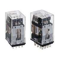
Magnetic Latching Version of G2A Ideal for Sequence Control
* Information in this page is a reference that you created on the basis of information in the product catalog before the end of production, may be different from the current situation, such as goods for / supported standards options / price / features of the product. Before using, please check the compatibility and safety system.
Related Contents
- Features
- Lineup
- Specifications
- Dimensions
- Catalog / Manual / CAD / Software
last update: September 24, 2012
Coil Ratings
| Rated
voltage |
Set coil | Reset coil | Set
voltage |
Reset
voltage |
Max.
voltage |
Power
consumption |
|||||
|---|---|---|---|---|---|---|---|---|---|---|---|
| Rated current | Coil re-
sistance |
Rated current | Coil re-
sistance |
Set
coil |
Reset
coil |
||||||
| 50 Hz | 60 Hz | 50 Hz | 60 Hz | ||||||||
| 12 VAC | 162 mA | 158 mA | 28 Ω | 40 mA | 39 mA | 125 Ω | 80%
max. of rated voltage |
80%
max. of rated voltage |
110%
of rated voltage |
Approx.
1.6 to 2.0 VA |
Approx.
0.5 to 1.2 VA |
| 24 VAC | 66 mA | 64 mA | 145 Ω | 22.6 mA | 22 mA | 460 Ω | |||||
| 50 VAC | 34 mA | 33 mA | 590 Ω | 11.3 mA | 11 mA | 1,900 Ω | |||||
| 100 VAC | 19 mA | 18.5 mA | 2,150 Ω | 12.3 mA | 12 mA | 3,600 Ω | |||||
| 6 VDC | 360 mA | 14 Ω | 160 mA | 32 Ω | Approx.
2.0 to 2.2 W |
Approx.
1.0 to 1.2 W |
|||||
| 12 VDC | 170 mA | 65 Ω | 85 mA | 125 Ω | |||||||
| 24 VDC | 85 mA | 270 Ω | 50 mA | 460 Ω | |||||||
| 48 VDC | 44 mA | 1,050 Ω | 24 mA | 1,900 Ω | |||||||
Note: 1. The rated current and coil resistance are measured at a coil temperature of 23°C with tolerances of +15%, –20%
for AC rated current and ±15% for DC coil resistance.
2. The AC coil resistance values are for reference only.
3. Performance characteristics data are measured at a coil temperature of 23°C.
4. The rated current of the AC operating coil is half-wave rectified current and is measured with a DC ammeter.
5. The peak reverse-breakdown voltage of the built-in diode is 1,000V.
6. The set coil of the Relay rated at 6 VDC is of the 5-minute rating. However, when it is used by connecting a diode
is series, it can be of the continuous rating.
7. By connecting an external resistor to each of the set and reset coils as shown in the table below, the rated current
of the Relay can be increased.
8. The maximum voltage is one that is applicable instantaneously to the Relay coil at 23°C and not continuously.
| Rated voltage | Connected coil voltage | External resistor | |||
|---|---|---|---|---|---|
| Set coil | Reset coil | ||||
| Resistance | Capacity | Resistance | Capacity | ||
| 110 VAC | 100 VAC | 0.27 kΩ | 0.5 W min. | 0.39 kΩ | 1/4 W min. |
| 200 VAC | 100 VAC | 2.7 kΩ | 5 W min. | 8.2 kΩ | 3 W min. |
| 220 VAC | 100 VAC | 3.3 kΩ | 6 W min. | 9.1 kΩ | 3 W min. |
| 100 VDC | 48 VDC | 1.1 kΩ | 10 W min. | 2.0 kΩ | 6 W min. |
Note: Use a resistor having the above resistance value with tolerances of ±10% for external connection.
Method of Connection
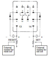
- Reset side
DC coil: Connect terminal No. 13 to terminal No. 9 or No. 13 to No. 5.
AC coil: Connect terminal No. 13 to terminal No. 5. - Set side
DC coil: Connect terminal No. 14 to terminal No. 12 or No. 14 to No. 8.
AC coil: Connect terminal No. 14 to terminal No. 8.
Contact Ratings
| Load | Resistive load (cosφ = 1) | Inductive load (cosφ = 0.4) (L/R = 7 ms) |
|---|---|---|
| Contact type | Crossbar bifurcated | |
| Contact material | Movable: Au-clad AgPd
Fixed: AgPd |
|
| Rated load | 0.3 A at 110 VAC
0.5 A at 24 VDC |
0.2 A at 110 VAC
0.3 A at 24 VDC |
| Rated carry current | 3 A | |
| Max. switching voltage | 250 VAC, 125 VDC | |
Characteristics
| Contact resistance
(see note 2) |
100 mΩ max. |
|---|---|
| Set time
(see note 3) |
AC: 25 ms max.; DC: 15 ms max. |
| Reset time
(see note 3) |
AC: 25 ms max.; DC: 15 ms max. |
| Min. pulse width | AC: 50 ms; DC: 30 ms |
| Max. operating frequency | Mechanical: 18,000 operations/hour
Electrical: 1,800 operations/hour (under rated load) |
| Insulation resistance
(see note 4) |
100 MΩ min. (at 500 VDC) |
| Dielectric strength | 1,500 VAC, 50/60 Hz for 1 minute between coil and contact (700 VAC between contacts
of same pole) (1,000 VAC between set and reset coils) |
| Vibration resistance | Destruction: 10 to 55 to 10 Hz, 0.75 mm single amplitude (1.5 mm double amplitude)
Malfunction: 10 to 55 to 10 Hz, 0.5 mm single amplitude (1.0 mm double amplitude) (for contact malfunction); 3.0-mm double amplitude (for armature malfunction) |
| Shock resistance | Destruction: 1,000 m/s2
Malfunction: 100 m/s2, 300 m/s2 |
| Endurance | Mechanical: 100,000,000 operations min. (at operating frequency of 18,000 operations/
hour) Electrical: 5,000,000 operations min. (under rated load and at operating frequency of 1,800 operations/hour) (see note 5) |
| Error rate (level P)
(Reference value) (see note 6) |
1 mA at 100 mVDC |
| Ambient temperature | Operating: -10°C to 40°C (with no icing or condensation) |
| Ambient humidity | Operating: 5% to 85% |
| Weight | Approx. 38 g |
Note: 1. The data shown above are initial values.
2. The contact resistance was measured with 0.1 A at 5 VDC using the fall-of-potential method.
3. The set or reset time was measured with the rated voltage imposed with any contact bounce ignored at an
ambient temperature of 23°C.
4. The insulation resistance was measured with a 500-VDC megger applied to the same places as those used
for checking the dielectric strength.
5. The electrical endurance was measured at an ambient temperature of 23°C.
6. This value was measured at a switching frequency of 60 operations per minute.
last update: September 24, 2012
 Product Category
- Relays
-
General Purpose Relays
-
Discontinued
- G2AK
-
Discontinued
-