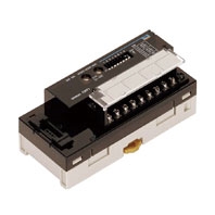
CRT1-TS04T / TS04P
Temperature Input Units
High-speed Transfer of Temperature Data with CompoNet. Enhanced Smart Functions.
Related Contents
- Features
- Lineup
- Specifications
- Dimensions
- Catalog / Manual / CAD / Software
last update: October 17, 2012
Basic Performance Specifications
| Item | Specification |
|---|---|
| Communications power supply voltage | 14 to 26.4 VDC |
| I/O power supply voltage *1 | 20.4 to 26.4 VDC (24 VDC -15%/+10%) |
| Noise immunity | Conforms to IEC 61000-4-4, 2 kV (power line). |
| Vibration resistance | 10 to 60 Hz with double-amplitude of 0.7 mm, 60 to 150 Hz and 50 m/s2 in
X, Y, and Z directions for 80 min each |
| Shock resistance | 150 m/s2 (3 times each in 6 directions on 3 axes) |
| Dielectric strength | 500 VAC (between isolated circuits) |
| Insulation resistance | 20 MΩ min. (between isolated circuits) |
| Ambient operating temperature | -10 to 55°C |
| Ambient operating humidity | 25% to 85% (with no condensation) |
| Ambient operating atmosphere | No corrosive gases |
| Storage temperature | -25 to 65°C |
| Storage humidity | 25% to 85% (with no condensation) |
| Terminal block screw tightening
torque *2 |
M3 wiring screws: 0.5 Nm
M3 mounting screws: 0.5 Nm |
| Installation | Mounted on 35-mm DIN Track or Mounting Bracket, or secured with M4
screws (depending on model) |
*1 The I/O power supply is called the sensor power supply in information for the CRT1-VAD04S.
*2 Applicable only to Slaves to which screw terminal blocks are mounted.
Specifications
| Model | CRT1-TS04T | CRT1-TS04P | |
|---|---|---|---|
| Input type | Switchable between R, S, K, J, T, E, B, N, L, U, W, and PL2
When set with CX-Integrator: Input types can be set individually for each input. Wen set with DIP switch: The same input type setting applies to all 4 inputs. |
Switchable between PT100 (-200
to 850°C) and PT100 (-200 to 200°C) When set with CX-Integrator: Input types can be set individually for each input. When set with DIP switch: The same input type setting applies to all 4 inputs. |
|
| Indicator accuracy | (±0.3% of indication value or ±1°C, whichever is larger) ±1
digit max. Indicator Accuracy in Exceptional Cases |
-200 to 850°C input range:
(±0.3% of indication value or ±0.8°C, whichever is larger) ±1 digit max. -200 to 200°C input range: (±0.3% of indication value or ±0.5°C, whichever is larger) ±1 digit max. |
|
| Input type and
temperature range |
Input accuracy | ||
| K, T, and N below
-100°C |
±2°C ±1 digit max. | ||
| U and L | ±2°C ±1 digit max. | ||
| R and S below 200°C | ±3°C ±1 digit max. | ||
| B below 400°C | Not specified. | ||
| W | ±0.3% of indication value or ±3°C
(whichever is larger) ±1 digit max. |
||
| PL2 | ±0.3% of indication value or ±2°C
(whichever is larger) ±1 digit max. |
||
| Conversion cycle | 250 ms/4 points | ||
| Temperature
conversion data |
Binary data (4-digit hexadecimal when Normal Display Mode is selected or 8-digit hexadecimal
when 1/100 Display Mode is selected.) |
||
| Isolation method | Between input and communication lines: Photocoupler isolation
Between temperature input signals: Photocoupler isolation |
||
| Mounting method | 35-mm DIN track mounting | ||
| Communications
power supply current |
75 mA max. at 24 VDC
110 mA max. at 14 VDC |
75 mA max. at 24 VDC
110 mA max. at 14 VDC |
|
| Weight | 148 g max. | 147 g max. | |
Effects of Mounting Direction on Accuracy
A cold junction compensator is included in the Terminal Block of the CRT1-TS04T. The input accuracy depends on the mounting direction if only the Unit is replaced.
| Mounting direction | Input accuracy | |
|---|---|---|
| Mounted normally | As specified in the Performance Specifications. | |
|
Mounted in any direction other than the above |
±0.3% of indication value or ±2°C (whichever is larger) ±1 digit max. Indicator Accuracy in Exceptional Cases |
|
| Input type and temperature range | Input accuracy | |
| K, T, and N below -100°C | ±3°C ±1 digit max. | |
| U and L | ±3°C ±1 digit max. | |
| R and S below 200°C | ±4°C ±1 digit max. | |
| B below 400°C | Not specified. | |
| W | ±0.3% of indication value or ±4°C (whichever is larger) ±1 digit max. |
|
| PL2 | ±0.3% of indication value or ±3°C (whichever is larger) | |
last update: October 17, 2012